


Machining Spline on Shaft: Complete CNC Manufacturing Process Guide
Machining Spline on Shaft is a precise production process that makes teeth or ridges that run along the surface of a shaft. This lets power systems reliably transfer energy. Unlike simple locked joints, splined shafts spread loads across many teeth, which stops stress from building up and failure before it's time. To get ISO 6 Grade accuracy, this process uses advanced CNC methods like hobbing, milling, and grinding. Splined shafts are made from 45# steel to SAE4340 and are hardened by heat processes like carburising or induction hardening. They play important roles in robotic joints, hydraulic pumps, precision gears, and automobile drivelines that need to have zero backlash and a small size.
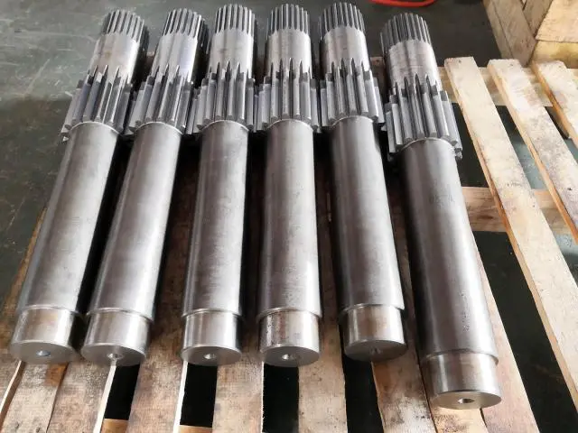
Understanding Splines on Shafts
What Makes Splined Shafts Different from Keyways?
When engineers look at ways to send power, they need to be able to tell the difference between splines and keyways. A keyway depends on a single wedge-shaped part being inserted into slots on both the shaft and the hub that are the same size and shape. This design is simple and cheap, but it puts a lot of stress on the key edges, which limits the torque and creates possible failure points when the load is cycled.
Splined joints, on the other hand, have many teeth that are cut right into the shaft surface. This shape spreads rotational loads evenly across all engaging teeth, greatly improving the load-carrying capacity without making the shaft bigger. Because involute spline profiles are self-centering, radial runout is kept to less than 0.01mm. This makes them perfect for high-speed uses that go over 15,000 RPM, like electric car transmissions and aerospace actuators.
Common Spline Profile Types and Their Selection Criteria
1. Involute Splines: These profiles use mathematics from the idea of involute gears to make pressure angles that stay the same when the gears connect. One thing that makes manufacturing flexible is that the same bit can cut teeth with different numbers, which lowers the cost of tools. When misalignment tolerance and smooth power transfer are important, involute splines are used a lot in automobile driveshafts and servo motor couplings. Pressure angles are usually between 30° and 37.5°. 30° gives roots more strength, while 37.5° makes them more center.
2. Parallel-Sided Splines: These have rectangular tooth shapes and parallel sides. They are also known as straight-sided splines. They are easier to measure with go/no-go scales and are good for situations where making things is more important than getting them perfectly centred. Heavy machinery and mining equipment often use parallel splines because they can handle shock loads well, but they make a little more friction than involute designs.
3. Internal versus External Splines: External splines are made on the outside diameters of shafts, while internal splines are cut into holes or hubs. Machining internal features is more difficult because you can't get to the tools as easily, chips are harder to get out, and verification is more complicated. These problems raise costs by 30 to 50 percent. Broaching is still the most common way to make internal splines, but improvements in CNC skiving have made other methods competitive for large-scale production.
Critical Design Parameters Engineers Must Specify
Material selection strongly affects spline performance: case-hardened steels like 20CrMnTi or 18CrNiMo7 (58–62 HRC) suit high-load applications, while 42CrMo (45–50 HRC) fits medium duty and SAE 4340 offers low-temperature toughness. Design parameters include module (0.5–50), tooth count, and pressure angle, balancing strength and manufacturability. Proper spline length (1.5–2.5× width) and helical angles improve durability, reduce wear, and control vibration.
Complete CNC Machining Process for Splines on Shafts
Raw Material Preparation and Pre-Machining Operations
The Machining Spline on Shaft process starts with choosing the materials and getting the blank ready. Forged blanks have better mechanical qualities and grain flow than bar stock. This means that there are fewer internal pressures that could cause the metal to warp during heat treatment. After being forged, blanks are normalised at 850–900°C to get rid of any remaining stresses and make the microstructure uniform.
After this, CNC turning processes set up important reference surfaces. To within ±0.02mm, operators make the outer diameters, end faces, and centring holes. Because these areas are used as starting points for everything that comes after, their consistency is very important. Centers or chucks hold workpieces in place while spline cutting, so errors in concentricity here lead directly to changes in the tooth profile.
During pre-machining, keyways are cut, oil tubes are drilled, and shoulders or flanges are made according to the plan. Leaving 0.5 to 1 mm of stock on the major diameters of splines lets them be ground after being heated, which makes up for the distortion caused by the heat. Strategic sequencing cuts down on the number of times setups have to be done, which lowers the number of placement mistakes and raises the level of stability in dimensions across production runs.
CNC Spline Cutting Methods and Tooling Considerations
1. Hobbing: A helical cutting tool that looks like a worm gear is used in this method of making. As the hob moves along the shaft axis, it rotates and cuts all the teeth one by one through synchronised motion. CNC gear hobbing machines can make 50 to 200 parts per shift, based on the size of the module. This makes this method cost-effective for batches larger than 100 units. Closed-loop servo control in modern CNC systems keeps the tooth spacing accurate to within 0.01 mm.
2. Milling: For cutting, splines can be made one tooth at a time on CNC milling machines that have form cuts or indexing heads. Milling is better for making prototypes, big modules (more than 20), and low-volume special orders, but it is slower than hobbing. Five-axis CNC mills can make complex shapes like crowned teeth. A small curve along the length of the tooth can accommodate an angle misalignment, which increases the service life of articulated drivelines.
3. Shaping: Splines are made by reciprocating cutting tools, which move in a way that looks like gears. Internal splines and blind-ended features are good for shaping because hobbing tools can't get out of them. Since shaping is a middle-ground method for making medium-batch internal splines, its production speeds are between those of hobbing and milling.
Tooling selection influences both quality and cost. Carbide-tipped hobs stay sharp through more than 5,000 parts, which makes the three times higher cost over high-speed steel worth it in mass production. When working with high-alloy steels like 40CrNiMo, coatings like TiAlN cut down on friction and make tools last 40% longer.
Heat Treatment Processes for Enhanced Durability
Heat treatment improves spline durability by tailoring hardness and toughness for different applications. Carburising forms a hard outer case (58–62 HRC) with a tough core (30–40 HRC), ideal for high-load environments. Through-hardening provides uniform 45–50 HRC for medium-duty use, while tempering adjusts properties. Induction hardening selectively strengthens tooth surfaces quickly, improving efficiency and maintaining a shock-absorbing core.
Precision Grinding and Final Finishing Operations
Heat treatment often causes spline tooth distortion, which is corrected through precision grinding removing 0.1–0.3 mm stock to restore accuracy. CNC grinding with CBN wheels achieves ±0.005 mm tolerance and 0.4 μm surface finish, while preventing grinding burns via controlled cooling. Crowning improves misalignment tolerance, and finishing processes like phosphating and superfinishing enhance corrosion resistance and reduce friction, adding 2–3 days to production but improving durability.
Quality Inspection and Measurement Techniques
Dimensional inspection combines pin gauges, CMM measurement, and CAD comparison to verify spline accuracy, with CMM achieving up to 2 μm precision. Composite testing using master gears evaluates real-world fit and runout, detecting errors beyond single-tooth measurements. Non-destructive methods like magnetic particle inspection and Barkhausen noise analysis detect surface and subsurface defects, ensuring reliability for critical aerospace and medical applications.
Choosing the Best Spline Shaft Machining Method: CNC vs Traditional Techniques
Why Traditional Methods Face Growing Limitations
In the past, specialised broaching tools and mechanical gear shapers were used a lot for Machining Spline on Shaft parts. Broaching is a fast and effective way to get a smooth surface. A single stroke can finish a spline in 15 to 30 seconds. What's the catch? Broach tools are made for a specific profile and take 8 to 12 weeks to make. They cost $3,000 to $15,000 per size. Design changes or special requirements mean that new tools are needed, which can be expensive and take a lot of time. This makes it hard for R&D teams to look into optimisation.
When using indexing heads for manual milling, skilled operators are needed and each part takes hours to make. Human factors, such as sorting mistakes, tool wear, and differences in how machines are set up between workers, can cause inconsistencies. Quality checks on splines that were cut by hand show tooth spacing differences of up to 0.08 mm, which is too big for servo motor uses where backlash needs to be less than 0.02 mm.
CNC Machining Advantages for Modern Procurement
Software-controlled precision and flexibility in CNC technology have changed the way spline parts are made. Digitised programs allow exact replication across production batches that are separated by months or years, which is very important for replacement parts that are sold after the originals break. The tightest tolerance is ±0.005mm, which meets ISO 6 Grade standards without the need for any extra work.
Scalability turns out to be life-changing. Tooling costs stay low, so prototype quantities of 5–10 pieces are still affordable. Standard hobs and cutters can handle a wide range of sizes. When the number of items being made goes up, the same CNC equipment can easily switch to batch production without having to spend more money on new equipment. Purchasing managers like this level of freedom; spreading the cost of tools over a larger number of different part numbers lowers overall costs.
Less time spent on setup is good for your schedule. CAM software automatically creates toolpaths from CAD models, which cuts the time needed to program from days to hours. Quick-change fixturing systems let workers switch between part numbers in less than 15 minutes. This makes mixed-model production schedules possible, which are becoming more common in lean manufacturing settings.
Decision Framework for Method Selection
Method selection depends primarily on production volume, complexity, and material hardness. For under 50 units, CNC milling or hobbing is preferred; 50–500 units suit CNC hobbing, while over 500 units justify broaching or rolling due to amortized tooling costs. Complex geometries require CNC 5-axis machining. Hard materials above 45 HRC need hard hobbing or profile grinding, with longer lead times of up to two weeks.
Procurement Considerations for Custom Machined Spline Shafts
Evaluating Supplier Capabilities and Certifications
When choosing a Machining Spline on Shaft manufacturer, you need to look at their technical capabilities and quality control systems. The inventory of machine tools shows what kinds of things can be made. For example, facilities that don't have CNC grinding equipment can't do precise finishing after heat treatment. Find out what kinds of CNC models they have, how fast their spindles go, and what kind of measure tools they have. These days, companies keep their own coordinate measuring machines (CMMs), gear analysers, and material testing labs in-house rather than outsourcing inspections.
Although ISO 9001 certification shows structured quality management, standards that are specific to a sector are more important. The car supply lines are covered by ISO/TS 16949 (now IATF 16949), which requires process capability studies, PPAP (Production Part Approval Process) documentation, and traceability tools. Aerospace suppliers need to be certified to AS9100, which focuses on controlling configurations and avoiding foreign object debris (FOD).
Production knowledge is very important. A company that has been making gears and splines for 15 years has seen and fixed the small problems that stop new companies from starting up. Over thousands of production runs, heat treatment distortion patterns, the best ways to grind certain alloys, and fixturing methods that reduce runout become clear. This deep process knowledge is shown by YIZHI MACHINERY's history of more than ten years.
Understanding Cost Drivers and Budget Planning
Material selection is a major cost driver, with prices ranging from low-cost steels (45# at $800–$1,200/ton) to aerospace alloys like SAE 4340 exceeding $4,000/ton, typically accounting for 25–40% of total part cost. Manufacturing complexity adds further cost, with internal splines, tight tolerances, and special profiles increasing machining expenses by 20–50%. Heat treatment, finishing, and coatings also add significant per-part costs. Higher production volumes and blanket orders can reduce unit prices by up to 60% through economies of scale.
Requesting Effective Quotes and Technical Communication
Clear technical communication prevents delays and cost overruns by providing full CAD models (STEP/IGES), defined spline standards (ANSI, DIN, or ISO), and detailed requirements for materials, heat treatment, hardness, and coatings. Quality expectations should include certifications, inspection reports, and FAI documentation when needed. Lead times must be realistic: standard parts take ~35–45 days, while custom designs require 50–60 days including machining, heat treatment, and inspection stages.
Ensuring Long-Term Performance: Stress Analysis and Maintenance of Splined Shafts
Load Types and Failure Mechanisms
Spline shafts are subjected to torsion, bending, and high contact pressures during operation, with torsion being the dominant load causing shear at tooth roots. Misalignment introduces additional tensile and compressive stresses, while contact pressures can reach 1500–2500 MPa. Failures mainly arise from fatigue, where cracks initiate at stress concentration points and propagate until fracture. Fretting corrosion also occurs due to micro-movements, producing oxide debris and accelerating wear and potential connection loss.
Engineering Analysis Methods for Design Validation
Finite Element Analysis (FEA) is used to predict stress distribution in spline designs under real loads such as torque and bending, helping identify critical stress points and safety factors. AGMA standards provide analytical formulas to verify bending, shear, and compressive stresses for quick validation. Rapid life testing under cyclic loads confirms durability, while test data is used to refine and improve FEA accuracy for future designs.
Practical Maintenance and Inspection Guidelines
Regular inspections help detect early spline wear through visual checks and listening for abnormal noises like grinding or clicking. Signs such as heat discoloration, pitting, or fretting indicate developing faults. Dimensional checks using go/no-go tools confirm wear limits; replacements are needed if tooth loss exceeds 0.1 mm or backlash increases. Proper lubrication, especially EP greases, is essential, with intervals of 500–2,000 hours depending on conditions.
Conclusion
By learning the ins and outs of Machining Spline on Shaft, procurement professionals and engineers can choose parts that will work reliably for the duration of their useful lives. Making smart decisions lowers risk and raises profits. This includes knowing about design factors like involute profiles and pressure angles and how to use CNC production processes like hobbing, heat treatment, and precise grinding. Your power transmission systems will meet high standards if you choose suppliers with a track record of success, complete quality systems, and the ability to adapt to specific needs. YIZHI MACHINERY has been making precision parts for 15 years and uses ISO-compliant methods to deliver components that solve difficult engineering problems in aerospace, automotive, and industrial settings.
FAQ
1.What determines whether to use hobbing or milling for spline production?
Batch quantity stands as the primary decision factor for Machining Spline on Shaft. Hobbing has shorter cycle times—50 to 200 parts per shift—so it's cost-effective for orders of more than 100 units per year. The process uses generating motion, in which the hob turns while feeding along the axis of the shaft, cutting each tooth one at a time. Milling works well for making prototypes and small custom orders (less than 50 units), especially when the spline has crowning, broken tooth patterns, or non-standard shapes that need five-axis CNC capabilities. Through indexing, milling cuts one tooth space at a time. This gives you more options, but it takes longer to do. The hardness of the material also affects the choice of method. For example, pre-hardened shafts above 45 HRC need to be hard-hobbed with carbide skiving cutters or ground, since regular hobbing tools can't cut hardened surfaces.
2.How do carburizing and induction hardening differ in application?
By diffusing carbon at 850–950°C and then cooling, carburising makes a tough case (58–62 HRC) on top of a hard core (30–40 HRC). This treatment is good for things that need to be very resistant to surface fatigue and very tough when hit, like driveshafts in cars and robotic joint splines that are under shock loads. Case depths between 0.8 mm and 1.5 mm are good for millions of torque cycles before they start to wear out. Induction hardening specifically hardens spline teeth by using electromagnetic heating and fast quenching. It only takes seconds to finish, while carburising takes 6 to 12 hours. Induction works best when through-hardening isn't needed and warping needs to be kept to a minimum. Spindles for machine tools and shafts for hydraulic pumps are two examples of these types of parts. When surface hardness needs (usually 50–55 HRC) are lower than what carburising can handle, induction hardening is a better option because it uses less energy and has less of an effect on the environment.
3.What tolerances can CNC machining realistically achieve for splined shafts?
Modern CNC gear hobbing and grinding machines regularly achieve ISO 6 Grade accuracy, which means that tooth profile differences are less than 0.005mm and tooth spacing mistakes are less than 0.01mm. For servo motor joints, precision gearbox shafts, and aircraft actuation systems where backlash needs to stay below 0.02mm, these standards work well. To get tighter tolerances (ISO 5 or better), grinding after heat treatment with CBN wheels and temperature-controlled manufacturing environments is needed. This level of accuracy raises costs by 40 to 60 percent, but it's needed for very fast uses (above 20,000 RPM) or positioning systems that need consistency within an arc second. CMM verification proves the real sizes and creates inspection reports that show the item meets the tolerances that were set.
Partner with YIZHI MACHINERY for Precision Spline Manufacturing Solutions
YIZHI MACHINERY stands ready as your trusted Machining Spline on Shaft manufacturer. They make custom parts that meet the strict needs of precision gearbox assemblies, robotic joints, and hydraulic systems. We can do forging, CNC hobbing, heat treatment, and hard grinding, among other things. We can make splined shafts in modules from 0.5 to 50 with a surface hardness of up to 62 HRC. Our 35–60 day production schedules work for both prototype development and batch production, and our ISO-certified quality systems make sure that every part meets your needs. With real-time tracking and a one-year warranty, customised packaging with shock-absorbing liners will keep your investment safe during global shipping. Contact our technical team at sales@yizmachinery.com to talk about your specific needs, whether you need SAE4340 aerospace-grade shafts or 42CrMo solutions for industrial equipment that are the most cost-effective. We accept low minimum order amounts and offer full design help to turn your ideas into reliable, high-performance products.
References
1. American Gear Manufacturers Association. (2018). AGMA 6123-B06: Design Manual for Enclosed Epicyclic Metric Module Gear Drives. Alexandria, VA: AGMA Publications.
2. Deutsche Institut für Normung. (2015). DIN 5480-1:2006: Involute Splines Based on Reference Diameters – Part 1: Generalities. Berlin: Beuth Verlag.
3. Budynas, R.G., & Nisbett, J.K. (2020). Shigley's Mechanical Engineering Design (11th ed.). New York: McGraw-Hill Education.
4. Society of Automotive Engineers. (2017). SAE J498: Splines – Involute, Side Fit, Full Fillet Root. Warrendale, PA: SAE International.
5. Klocke, F., & König, W. (2014). Gear Cutting: Fundamentals, Tools, and Machines. Berlin: Springer-Verlag.
6. Townsend, D.P. (2012). Dudley's Handbook of Practical Gear Design and Manufacture (2nd ed.). Boca Raton, FL: CRC Press.

USER EVALUATE
Here is the customer's evaluation of us