


Worm Gear Reducers: Basic Working And Advantages
When industrial machinery needs to multiply power reliably while taking up little space, worm gear reducers are the only way to go. A Worm Gearbox Reducer is made up of a threaded worm shaft and a worm wheel that fits on top of it. It lowers the speed and increases the power at right angles, which makes it perfect for use in conveyors, lifting equipment, and automatic production lines. This mechanism solves some of the most important operational problems: it can achieve high reduction ratios of up to 100:1 in small spaces; it keeps power transmission smooth with little vibration; and it automatically locks itself for better safety in vertical applications in the mining, aerospace, and industrial machinery sectors.
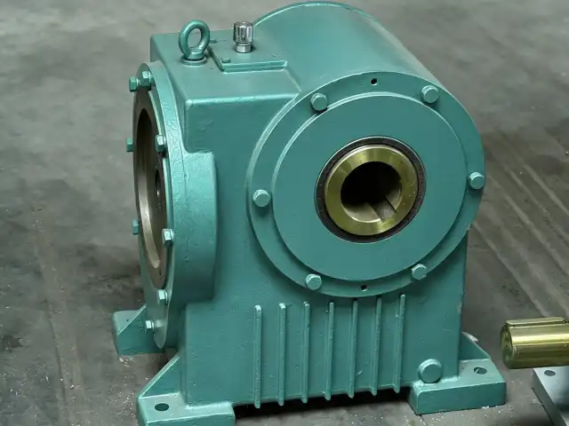
Understanding How Worm Gear Reducers Work
A worm screw and a worm wheel that are placed perpendicular to each other must precisely mesh in order for these reducers to work. When the worm turns, its helical threads join the wheel's teeth. This slows down the input rotational speed and increases the output force equally. This sliding contact device allows for orthogonal power transfer, which makes it easier to set up tools in tight spaces.
Material Selection and Durability
Premium material choices determine how long a reduction will last. We make worm shafts at YIZHI MACHINERY from hardened alloy steels like 20CrMnTi, 42CrMo, and AISI4140. The steels are heated through carburising and cooling processes that make the surface hard, which is between 58 and 62 HRC. Bronze metals are used in the worm wheels because they have the right amount of wear protection and friction. This combination of materials keeps the dimensions stable even under continuous loads and reduces scuffing. Our precision grade meets ISO 8-9 standards, which means that the meshing shape will be the same across customised modules with a size range of 1 to 50.
Gear Ratios and Performance Characteristics
Output parameters are directly affected by reduction ratios. Lower ratios, like 7:1, give you about 85–90% mechanical efficiency, which is good for situations where speed is more important than torque multiplication. When the ratio gets close to 60:1, efficiency drops to 50–60%, but the torque density is great for lifting equipment and machine tool indexing mechanisms. The ratio choice strikes a balance between the need for operational speed and the heat that is produced by sliding friction. When engineers set ratios to keep thermal overload from happening in continuous-operation situations that happen a lot on mine conveyors and aircraft ground support equipment, they have to look at job cycles and the environment.
Noise Reduction Through Design
The lack of noise during operation is due to constant tooth contact, not the impact loading that happens in spur gears. Our cutting, hobbing, milling, and grinding methods ensure precise gear geometry, which makes sure that contact patterns are regular and vibration-induced noise is kept to a minimum. The choice of lubricant also affects how well the sound works. For example, synthetic polyalphaolein oils make hydrodynamic films that lower mesh frequencies. Micro-irregularities that cause high-frequency sound are reduced by our grooved surface finishing methods. This means that these Worm Gearbox Reducer can be used in noise-sensitive industry settings where sound levels must stay below 70 decibels during full-load operation.
Key Advantages of Worm Gear Reducers for Industrial Use
Worm gear reducers have unique benefits that help procurement managers and maintenance engineers in many different industries with their most important operational problems. Knowing these benefits helps make the case for investing money and shapes tactics for integrating new systems.
High Torque Capacity in Compact Enclosures
Modern industrial design is all about making the best use of space. These reducers have very small housings, but they can handle a lot of torque—a 100mm center-distance unit can reliably send over 2,000 Nm. The right-angle shape lets motors be mounted either parallel to conveyor lines or perpendicular to lift shafts, which saves valuable floor space in factories that are already full. This small size is very important in mining for uses where the equipment has to fit into narrow tunnels or on aerospace repair platforms with limited room.
Self-Locking Safety Feature
When lead angles stay below about 5 degrees, the worm gear reducer automatically locks into place, providing passive brakes. Back-driving resistance stops unplanned reverse movement when the machine is not moving. This is very important for lift traction machines and lifting equipment where load reversal could be dangerous. Because of this mechanical advantage, many applications don't need external brakes. This makes the system simpler and easier to maintain. But installations that are very important for safety should have two sets of brakes, because dynamic vibrations can be stronger than static friction coefficients while the system is working.
Smooth Operation with Minimal Vibration
Continuous sliding contact sends power smoothly, without the cycle loading spikes that come with tooth-impact gear systems. This feature helps automatic production line reducers that work with small items or precision positioning systems that need accuracy down to the micron level. When fitted correctly and oiled, vibration amplitudes are usually less than 3mm/s RMS, which is a lot less than similar helical gears working at the same loads. Less shaking increases the life of bearings, lowers the risk of structural fatigue, and raises the quality of products made in delicate ways that are common in industrial machines.
Here are the core advantages these devices bring to demanding environments:
- Reliable Overload Protection: The sliding mesh can handle short-term shock loads without catastrophic tooth failure. Instead of breaking gear teeth, it absorbs impact energy through controlled surface deformation.
- Customization Flexibility: YIZHI MACHINERY can meet specific needs by changing tooth counts, module specs, and housing configurations. They also have a low minimum order quantity that lets them make samples of a single unit.
- Extended Service Intervals: If you lubricate properly using the manufacturer's recommended oils and follow our strict manufacturing guidelines, your equipment will last longer than 20,000 hours under normal conditions.
These advantages collectively solve persistent production problems, such as limited space in retrofitted buildings, safety concerns during material handling, and the need for low-maintenance power transmission systems that can handle the harsh conditions found in mines and other outdoor industrial sites.
Worm Gear Reducer Applications in Global B2B Markets
These reducers are used in many different ways by businesses around the world. Their unique properties meet specific operating needs. Knowing the deployment environment helps procurement pros figure out which use cases are right.
Conveyor Systems and Material Handling
Worm gear reducers are used a lot in belt conveyors, roller tables and bucket elevators in factories and distribution centers. The right-angle drive arrangement puts motors next to conveyor frames, making it easier for repair workers to get to them while keeping the aisles wide. When belts are highly loaded, high starting torque can overcome static friction. This is especially helpful when emergency stops are made and the conveyors need to be restarted. Mining operations use toughened versions with better sealing to keep abrasive dust out. These machines work continuously underground, where access to services is limited, and dependability is very important.
Lifting and Positioning Equipment
Self-locking features are used to improve safety in lift traction machines, construction hoists and stage rigging systems. The mechanical benefit of 40:1 or 60:1 ratios lets you choose small motors while still keeping precise speed control, which is important for passenger comfort and accurate load placing. Aerospace ground support equipment uses these Worm Gearbox Reducer in aeroplane repair platforms and cargo loaders, where reliable operation during short periods of high load is more important than maximum mechanical economy. Repeatedly applying force to our surface-hardened parts doesn't speed up the wear process.
Comparison with Alternative Gearbox Technologies
When it comes to performance, worm gear reducers are different from helical, planetary, and bevel options. Helical gears are more efficient—often by more than 95%—but they need bigger spaces for the same ratios and can't automatically lock themselves. Planetary systems have a high power density and are very efficient, but they are very expensive and need a lot of complicated maintenance. When power is sent at a right angle, bevel gears work well, but they can't reach the high ratios that worm types can in a single stage. Instead of just looking at the original capital cost, procurement choices should take into account torque needs, space limitations, job cycles, and the total cost of ownership over the expected service life.
How to Choose the Right Worm Gear Reducer for Your Needs
To choose the best tools, you need to carefully compare the technical specs with the needs of the business and the supplier's abilities. Making well-informed choices keeps you from making costly mistakes and failing too soon.
Technical Specification Alignment
First, use the load mass, friction coefficients, and acceleration profiles to figure out how much output torque is needed. Match this torque demand to the right reducer ratings and service factors, which are usually between 1.5 and 2.0 for continuous industrial duty. Make sure that the input speed matches the motor choices that are available and that the output speed that is wanted meets the needs of the process. Material choices and seal requirements are affected by things like the temperature range, humidity levels, and the amount of contamination present. The engineering team at YIZHI MACHINERY helps with application research and makes sure that the chosen setups work within the thermal and mechanical design limits for as long as the expected service intervals.
Supplier Evaluation Criteria
In addition to product specs, choosing the right supplier has a big effect on long-term happiness. Check the company's ability to make things by looking at their ISO certification, the machines they have (like CNC gear machining centers and precision grinding tools), and their quality control methods (like noise spectrum analysis and thermal equilibrium testing). Production lead times are important. Our normal 35–60 day delivery schedules work with project deadlines and keep quality standards high. Customisation is important when standard catalogue items don't meet specific installation needs; we support customised module specifications, non-standard mounting configurations, and materials that are made to work in corrosive environments.
Total Cost Considerations
The price of the initial purchase is only one part of lifecycle economics. Think about the upkeep needs, such as how often to lubricate and how many new parts you expect to need. Energy efficiency has a direct effect on working costs. For example, a 70% efficient reducer that uses 10kW of input energy wastes 3kW as heat, which adds up to big power costs over many years of use. Our full customisation process, which includes communicating your needs, making design drawings, handling your order, inspecting for quality, packing, and shipping, makes sure that our pricing is clear and there are no secret fees. When problems happen, warranty coverage and quick technical help keep downtime costs to a minimum, protecting income streams and productivity.
Maintenance Tips and Efficiency Optimization
Proactive maintenance practices increase the return on capital investment by keeping performance parameters within specifications and extending the life of the system.
Lubrication Management
The choice of lubricant and how often it is replaced have a big effect on life. We suggest synthetic gear oils that meet the AGMA 9005-E02 viscosity grades for the temperature where the engine will be used, usually ISO VG 220 for mild areas. After 500 hours of use, the oil should be changed for the first time to get rid of break-in wear particles. After that, every 2,500 hours for natural oils or sealed-for-life configurations using synthetic formulas. Check the condition of the oil by taking samples from time to time and testing them for changes in viscosity, loss of additives, and contamination. Having the right amount of oil in the bearings and making sure they stay cool is important. The oil level should reach the middle of the sight glasses when the reducers are at full operating temperature.
Inspection Protocols
Inspections every three months find problems as they start to form before they become major problems. If the temperature rises more than 50°C above usual, it means that there isn't enough oil or the machine is overloaded. Changes in audio patterns should be noted; new grinding sounds could mean that the bearings are wearing out or that the gear mesh isn't working right. Check the backlash of the output shaft once a year; too much play means that the wear is getting worse and needs to be fixed. Check the seals for oil leaks that happen before bigger ones. Using accelerometers for vibration analysis can find problems with bearings and misalignment that can't be seen with the naked eye. Our technical support team helps customers with diagnostic procedures and setting the right levels of alerts to start maintenance tasks.
Efficiency Enhancement Strategies
There are ways to improve the performance of systems that are already in place. By switching to low-friction synthetic oils, you can get back 3–5% of your performance while lowering the temperature at which the machine works. Check that the input shafts of the motor and gear are lined up correctly. If they are not lined up properly, either angularly or parallelly, axial loads are created that speed up bearing wear and increase friction losses. Make sure that the mounting surfaces stay flat and stiff. Frames that are flexible or distorted can cause the housing to bend, which can mess up the optimised mesh shape. Think about doing a load profile study. If the real duty cycles are lighter than what was planned, using a reducer with a lower ratio such as a Worm Gearbox Reducer will make the system more efficient. Using data from operational tracking systems to make choices about optimisation that are based on facts can lower energy use and increase the time between maintenance visits at the same time.
Conclusion
Worm gear reducers have been used for a long time in industrial settings that need to multiply high torques, have small installation areas, and have effective self-locking safety features. Their operational benefits, such as noiseless gearbox, high overload tolerance, and smooth gearbox, solve important problems in the mining, aerospace, and industrial machinery sectors. Long-term performance and cost-effectiveness depend on the choice of materials, the accuracy of the manufacturing process, and the right maintenance methods. When you know the technical trade-offs between worm designs and other gearbox technologies, you can make smart purchasing choices that are in line with practical priorities, space limitations, and efficiency goals in global B2B markets.
FAQ
1.What maintenance intervals do worm gear reducers require?
Mineral-based lubricants should be changed every 2,500 hours under normal conditions, and the first oil change should happen after 500 hours of use to flush out break-in particles. Synthetic oils in protected housings may last the reducer's entire working life, which could be 20,000 hours or more. However, it is still recommended that the outside be inspected every three months. More frequent servicing is needed in harsh environments with extreme temperatures, high humidity, or rough contaminants.
2.Can worm gear reducers be customized for unique applications?
Of course. YIZHI MACHINERY specialises in custom setups that can fit non-standard module specs, different tooth counts, special materials for corrosive conditions, and different ways of fitting. We have low minimum order numbers that allow for everything from single prototypes to full production runs. We also offer full design advice services to back this up.
3.What factors influence operational noise levels?
Noise is caused by the accuracy of the gear mesh, the quality of the lubrication film, and the way the load is applied. When grinding is used instead of hobbing alone to achieve higher precision production, the tooth profile flaws that cause acoustic energy are reduced. Having enough grease stops vibrations from travelling. When loads are heavier, friction and contact forces rise, which raises sound levels. When units are properly set up and maintained, they usually run at less than 70 dB.
Partner with YIZHI MACHINERY for Reliable Worm Gearbox Reducer Solutions
YIZHI MACHINERY can help you with your power transfer needs by making Worm Gearbox Reducer solutions that are precisely designed and meet strict ISO standards. With 15 years of production experience, state-of-the-art CNC machining centers, and smart heat treatment lines, we can make sure that the parts we sell meet the strict requirements of industrial machinery, mining, and aerospace applications. We can customise everything, from talking about your original needs to making design models and producing things out of materials like 20CrMnTi and 42CrMo. We also do strict quality checks and offer global shipping with real-time tracking. As a reliable Worm Gearbox Reducer manufacturer, we offer 35–60 day wait times, unique packaging that keeps products safe during shipping, and a one-year guarantee with quick technical support. Contact us at sales@yizmachinery.com to talk about your specific torque needs, space limitations, and environmental conditions. We'll be happy to show you how our precision gear solutions can improve the performance and reliability of your machinery.
References
1. Buckingham, Earle. Analytical Mechanics of Gears. Dover Publications, 1988.
2. Dudley, Darle W. Handbook of Practical Gear Design and Manufacture. CRC Press, 2012.
3. American Gear Manufacturers Association. AGMA 6034-B92: Practice for Enclosed Cylindrical Wormgear Speed Reducers and Gearmotors. AGMA, 1992.
4. Deutsches Institut für Normung. DIN 3996: Calculation of Load Capacity of Cylindrical Worm Gear Pairs with Rectangular Crossing Axes. DIN Standards, 2019.
5. Radzevich, Stephen P. Dudley's Handbook of Practical Gear Design and Manufacture. CRC Press, 2016.
6. Lynwander, Peter. Gear Drive Systems: Design and Application. Marcel Dekker, 1983.

USER EVALUATE
Here is the customer's evaluation of us