


Working principles of girth gear and pinion
When huge industrial barrels need to turn while being loaded with huge amounts of weight, the Girth Gear and Pinion device is what makes it possible. A big ring gear is attached around the outside of moving equipment, and one or more smaller driving pinions are linked to motor assemblies. This special transmission system works by meshing the two. In contrast to normal gears, this arrangement transfers very high power at low rotational speeds, usually between 3 and 15 RPM. This makes it possible to move over 100 tons of equipment with precision. Gear teeth must fit together perfectly for the mechanism to work. The pinion's rotational force causes the much larger girth gear to rotate smoothly and continuously. This spreads mechanical load across many contact points to avoid problems in just a few places.
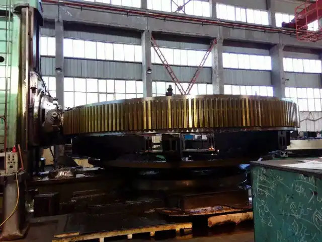
Understanding the Basics of Girth Gear and Pinion
Core Components and Their Functions
To make a transmission system for big rotary tools that works, you need to know how these huge parts interact with each other. The Girth Gear and Pinion is a big ring gear, sometimes several meters across, that goes around the spinning shell of mills, kilns, or dryers. This part has precisely cut teeth all the way around its outside, made to very tight tolerances that make sure it always makes touch with the moving element.
In this situation, the pinion gear is what moves things. The diameter of the pinion, which is attached to a different shaft and linked to motors and reduction gears, is usually between 200mm and 800mm. The difference in size between these two parts gives them the mechanical edge they need to move heavy things. When set up correctly, this system turns a motor's high-speed spinning into the slow, strong movement needed for processing materials.
Material Selection and Manufacturing Excellence
Picking the right materials has a direct effect on how long something works and how reliably it works. At YIZHI MACHINERY, we use high-quality materials like 42CrMo, AISI4140, 18CrNiMo7, and SAE4340 steel alloys to make these important parts. The core toughness and surface hardness of these materials are just right to survive constant contact stress and twisting forces.
Forging is the first step in our production process. This aligns the grain structure. Next, precision hobbing and milling are used to make correct tooth profiles. After that, the parts go through specific heat treatments, such as carburizing, cooling and tempering, or induction hardening, based on the needs of the application. Finishing the surface with hard chrome treatment or phosphating adds more protection against the corrosive conditions that are common in mine and cement production.
Working Principles of Girth Gear and Pinion
Torque Transmission Through Tooth Engagement
When you know how power moves through these huge systems, you can see why good specification is so important. As the motor turns the pinion shaft, spinning energy moves from the motor to the gear teeth. The point where two teeth meet makes a temporary link where forces press the tooth surfaces together. As the tooth turns, this compression zone moves along the tooth face. This makes it easy for power to flow from one pair of teeth to the next.
The speed decrease and torque increase are set by the Girth Gear and Pinion gear ratio, which is found by dividing the number of teeth on the girth gear by the number of teeth on the pinion. In a normal cement kiln, the ratio might be 150:1, which means that the wheel turns 150 times for every full turn of the kiln. This huge decrease makes it possible for motors and gears that aren't very big to run huge cylindrical vessels.
Load Distribution and Contact Mechanics
Spreading the load evenly across the tooth face keeps it from breaking too soon and greatly increases its useful life. The pressure angle, which is usually either 14.5° or 20°, changes how forces are split into radial and tangential parts. These days, 20° pressure angles are more common because they make it less likely that teeth will break under the shock loads that are common in mines.
The difference in strength between parts is an important factor in managing wear. The surface hardness of the pinions we make is between 58 and 62 HRC, and the surface hardness of the girth gears is usually between 45 and 50 HRC. Because of this difference, the harder pinion wears down the softer girth gear surface over time, creating the best contact pattern. This method keeps the bigger, more expensive girth gear safe while focusing wear on the cheaper pinions, which are smaller and easier to repair.
Common Challenges and Maintenance Tips for Girth Gear and Pinion
Typical Wear Patterns and Root Causes
Putting these drive systems to work in tough industrial settings will eventually break down. Understanding common failure modes helps maintenance teams come up with good ways to stop problems before they happen. Tooth surface pitting happens when continuous contact stress is higher than the material's failure limits. This makes small craters that get bigger over time. This pattern of wear usually means that the oil film is too thin or that there are contaminants in the grease.
Scuffing looks like linear scratches on the tooth face. It happens when metals touch each other and the lubricant film breaks down. This happens a lot in cement kilns, especially when they are cold and the viscous lubricants haven't hit their ideal flow qualities yet. Cracks usually start at the root of the tooth, where bending stresses are highest. These stresses are often caused by shock loading or flaws in the material.
Proactive Maintenance Strategies
To make a service last longer for the Girth Gear and Pinion, you need to do regular important upkeep tasks. Visually checking the tooth surfaces for strange wear patterns, measuring the backlash to find areas of extra clearance, and looking at the trend of vibrations to spot problems that are starting to form should all be part of regular inspection plans. We suggest that full inspections happen once a month for the first year of business and then every three months after that. This way, baseline performance can be set.
Management of lubrication needs extra care. For open gear materials to work properly, they need to keep their thickness over the whole temperature range while also being resistant to contamination and washoff. There are different ways to apply the lubricant, ranging from brushing by hand for small jobs to automatic spray systems that exactly measure the amount of lubricant that goes on the meshing zone. To keep metals from touching, the width of the lubricant film must be greater than the total hardness of the surfaces of both parts.
Practical Troubleshooting Guidance
When practical problems happen, systematic analysis is the best way to fix them. Noise that doesn't go along with vibrations is often a sign of tooth surface roughness caused by not enough lubricant. When noise and shaking happen together, they usually mean there are bigger problems, like fitting that isn't tight enough, bearing wear, or major tooth damage.
Monitoring temperature adds another layer of medical information. Most of the time, bearing housings work 20 to 40°C above room temperature. Readings above this range mean there is too much friction because the bearings aren't properly aligned, aren't oiled enough, or are wearing out. Thermal imaging cameras can quickly find trouble spots in big sites where checking the temperature by hand would not be possible.
Comparative Insights: Girth Gear and Pinion vs Other Gear Types
Performance Characteristics Across Gear Categories
Different gear setups meet different mechanical needs, which is why direct comparisons are useful for buying choices. Spur gears are easy to make and cost less because their teeth are straight to the shaft axis. They work well at modest speeds and loads, but they make more noise than helical options because all of the tooth faces connect at once instead of slowly.
Helical gears have angled teeth that connect more gradually, making the action easier and less noisy and vibrational. This arrangement works well for faster tasks, but it adds axial thrust loads that need thrust bearings to handle. The Girth Gear and Pinion system usually has either one or two helical tooth shapes to make it run smoothly and get rid of axial load.
Selection Criteria for Optimal Performance
To choose the right specifications, you have to match the skills of the parts to the needs of the work. When you figure out the load, you have to take into account both steady-state torque and shock factors that happen during starting and process problems. As rock falls through the shell of a mining ball mill, it causes a lot of impact loads. This means that the mills need to be built strong, with safety factors usually between 1.8 and 2.5.
The gear ratio choice matches the motor's features with the speed you want it to turn. The speed of a cement rotating kiln is usually between 2 and 4 RPM, so the reduction ratio needs to be between 100:1 and 200:1. When used to process rock, SAG mills may spin faster (8–12 RPM), which means they need less reduction.
Supplier Landscape and Procurement Considerations
There are many providers on the global market, and their skills and specialties range. Well-known brands like Rexnord, Schaeffler, and Timken offer styles that have been used in a lot of different situations. Their goods usually cost a lot, but they come with a lot of technical help and a history of how well they've worked.
YIZHI MACHINERY stands out from its competitors by offering a wide range of customization options and quick production times. With 15 years of experience making things and quality systems that are in line with ISO standards, we can give the same level of reliability as expensive brands while also being more flexible to meet specific needs. We can handle small orders, even ones that only need one machine, which is something that bigger makers usually turn down.
Procurement and Application Best Practices for B2B Buyers
Structured Approach to Online Sourcing
To make sure you get reliable, cost-effective results when you buy these important parts, you need to carefully consider your options. Start by writing down all the details of the application, such as the torque needs, the speed of spinning, the surroundings, and the size limitations. When you give providers clear instructions, they can come up with the right answers for you instead of general ones that might not work for the Girth Gear and Pinion.
Ask for full technical plans that include information about the materials, how they will be made, how they will be inspected, and quality records. Reputable providers are happy to be this open, but vague answers could mean there are problems with the quality. With every order, we send a lot of paperwork, like material approvals, heat treatment records, and data from dimensional inspections.
Key Questions for Supplier Assessment
By asking specific questions, you can find out how knowledgeable and skilled a seller really is. Find out about past projects that were done in your business, such as mining, cement, or industrial processes. Ask for case studies that show how to solve difficult problems in real life. The level of detail and complexity of answers show real experience rather than just a passing connection.
How reliable deliveries are is directly related to how much can be made. Find out what the production tools can do, such as the largest size limits for the gear hobbing machine, the maximum capacity of the heat treatment furnace, and the accuracy of the testing instruments. We keep up-to-date CNC gear machine centers, automatic grinding tools, and smart heat treatment lines that can work with parts ranging from small auxiliary drives to huge primary mill gears.
Maximizing Long-Term Return on Investment
Total lifecycle costs are part of strategic buying, not just the original purchase price. Components made to the highest standards of quality last longer before they need to be replaced. This saves money on both the cost of parts and the large amounts of money that are wasted on downtime, removal, installation, and production loses during maintenance periods.
Form relationships with providers who can offer more than just delivering products. We give you instructions on how to install, align, and lubricate the equipment so that it works at its best from the very beginning. As part of our global logistics support, we make tailored packing with materials that absorb shock and damage-prevention steps that keep transport damage rates below 0.1%.
Conclusion
Understanding how Girth Gear and Pinion systems work helps us understand why these strong transmission systems are so popular in big industry settings. Because they can handle thermal expansion and shell deflection and send huge amounts of power at low speeds, they can't be replaced in the cement industry, mining, or material processing. Depending on the right specifications, precise manufacturing, and preventative upkeep, these setups will either last for decades without breaking down or cause constant production problems. Teams in charge of buying things do well when they work with makers that have been around for a while and can offer proven knowledge, full customization options, and ongoing technical help throughout the lifecycle of the equipment.
FAQ
1. What makes girth gears different from standard transmission gears?
Girth Gear and Pinion assemblies are specially designed to fit around the edges of big spinning machines like kilns and mills. This makes it possible to have huge diameter ratios that aren't possible with other types of gear setups. This arrangement allows for huge increases in power while also allowing for the structural deflection and heat expansion that come with big rotating equipment. Split-gear designs are often used because they make it easier to put on existing buildings without taking them all apart.
2. How often should these transmission systems undergo inspection?
During the first year, new installations should have full checks every month to set a baseline for performance and find any problems with the installation early. Once stable operation is confirmed, checks every three months are usually enough. These inspections should include looking at the tooth surfaces visually, measuring backlash, looking at vibration trends, and checking the state of the lubrication. More regular maintenance may be needed in places with a lot of pollution or for heavy-duty tasks.
3. What factors most significantly impact operational lifespan?
The single most important factor is making sure that the orientation is correct during installation and upkeep throughout the service life. Misalignment puts a lot of pressure on the sides of the teeth, which speeds up wear by a huge amount. Proper greasing is also very important because it keeps protection films in place and keeps metals from touching each other. The natural durability is determined by the quality of the material and the accuracy of the heat treatment. Controlled startup procedures and preventing shock loads during operation protect the mechanical integrity.
Partner With YIZHI MACHINERY for Reliable Girth Gear and Pinion Solutions
Transmission parts that are made to last and be precise are needed for heavy industrial activities. For 15 years, YIZHI MACHINERY has been making custom Girth Gear and Pinion assemblies for use in mining, cement, and industry machines all over the world. Our production methods are in line with ISO standards and include advanced CNC machining, automatic grinding, and controlled heat treatment. The surface hardness is between 58 and 62 HRC, and the precision grades meet ISO 5-6 standards. We use high-quality materials like 42CrMo, AISI4140, and 18CrNiMo7 steel alloys, and we shape them by forging, hobbing, and precision cutting to make parts that can keep working well in tough situations. No matter if you need a single piece of new gear or a steady supply of it, our company can handle projects ranging from single units to large orders.
As a company that only makes girth gears and pinions, we offer full support from the initial design advice to the final delivery. This is backed by one-year guarantees and quick technical support. Our custom packing with shock-absorbing security and real-time shipment tracking makes sure that your important parts get to you on time and safely. Contact us at sales@yizmachinery.com to talk about your unique needs and find out how our flexible scheduling, ability to customize, and technical knowledge can help you get the most out of your equipment's performance and dependability.
References
1. American Gear Manufacturers Association. (2019). AGMA 2001-D04: Fundamental Rating Factors and Calculation Methods for Involute Spur and Helical Gear Teeth. Alexandria, VA: AGMA Publications.
2. Budynas, R.G., & Nisbett, J.K. (2020). Shigley's Mechanical Engineering Design (11th ed.). New York: McGraw-Hill Education.
3. Davis, J.R. (Ed.). (2005). Gear Materials, Properties, and Manufacture. Materials Park, OH: ASM International.
4. Deutschman, A.D., Michels, W.J., & Wilson, C.E. (2018). Machine Design: Theory and Practice (2nd ed.). New York: Macmillan Publishing.
5. Dudley, D.W. (1994). Handbook of Practical Gear Design and Manufacture. Boca Raton, FL: CRC Press.
6. International Organization for Standardization. (2013). ISO 1328-1:2013 Cylindrical Gears — ISO System of Flank Tolerance Classification. Geneva: ISO Standards.

USER EVALUATE
Here is the customer's evaluation of us