


Understanding Bevel Pinion Shafts: Key Insights and Applications
The Bevel Pinion Shaft is an important part of gearbox systems that need to precisely transfer torque between axes that cross each other. This single piece of machinery combines the functions of a bevel gear pinion and a driveshaft. It was designed to shift rotational power, usually at 90-degree angles, to heavy machinery, mining equipment, and accurate instruments. Unlike regular parallel-axis gearing, these parts solve problems with rotational gearbox while keeping operating efficiency above 95%. This makes them necessary for procurement managers and design engineers looking for reliable solutions for tough industrial settings.
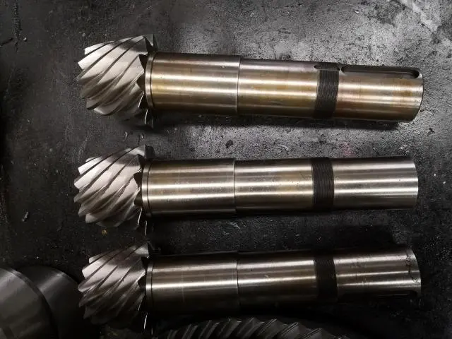
What Is a Bevel Pinion Shaft and How Does It Work?
Fundamental Design and Operating Principles
A Bevel Pinion Shaft is a single piece gearbox part where the pinion gear is built directly into the shaft body using precise casting techniques. This gets rid of the need for traditional keyed connections, which lowers the stress levels that usually lead to fatigue failures when loads are cycled. The part works as the driving input in bevel gear assemblies and meshes with bigger crown gears or ring gears to change the direction of rotation and the speed ratios.
The working part depends on carefully made tooth shapes that stay in contact while the device turns. When the pinion turns, its cone-shaped teeth engage the matching gear at exact angles, turning the torque input into motion output that is perpendicular to the input. This shape makes sure that the load is spread across multiple teeth at the same time, which greatly increases the power density compared to spur gear arrangements.
Tooth Geometry and Load Distribution Characteristics
How well a Bevel Pinion Shaft works depends a lot on how accurate the tooth profiles are. Surface roughness levels below Ra 0.8µm are reached through manufacturing processes like hobbing, milling, and precise grinding. This lowers friction coefficients and micropitting risks. Contact ratios are based on helix angles that range from 5° to 45°. Higher angles make connection easier but require more advanced machining skills.
Common Configuration Types and Selection Criteria
In industrial settings, three main configurations are used most often. When the load is modest, straight bevel forms are simple and cost-effective because the teeth are cut parallel to the cone angle. Spiral bevel types have curved tooth profiles that engage gradually, lowering noise levels by 10 to 15 decibels compared to straight types. This is important for automotive differentials and precision machinery. When the axes of a hypoid design are shifted, the pinion widths can be bigger, which increases the load capacity by 20 to 30 percent. However, extreme-pressure lubricants are needed because there is more sliding contact.
Buying decisions are based on knowing these differences. For mining breakers, straight bevels are more durable, but for machine tool spindles, sound dampening spiral shapes are needed. We make all three types using different materials, such as 18CrNiMo7, SAE4340, and AISI8620, depending on what you need for your business.
Key Applications and Advantages of Bevel Pinion Shafts
Industrial Sector Deployment Patterns
These gearbox parts solve certain angular power transfer problems in a number of different industries. In mining, cone crushers rely on Bevel Pinion Shafts to send huge amounts of torque from electric motors to eccentric assemblies while still being able to handle shock loads that are 200% of their nominal values. The built-in shaft design stops the fretting corrosion that happens in keyed assemblies that are constantly vibrating.
Material Science and Performance Optimization
The most common use for hypoid Bevel Pinion Shafts is in automotive differentials, where they lower the center of gravity of the vehicle by shifting the axes. Marine propulsion systems use versions that don't rust, often with special coatings, to move power from a vertical engine to horizontal propeller shafts that are submerged in saltwater. Aerospace control systems use small spiral bevel designs to save weight and cut down on noise, which justifies the higher costs of making them.
The choice of material has a direct effect on the load ability and service life. Case-hardening alloy steels with tough cores and wear-resistant surfaces are used in our production. During the process of carburising, carbon is spread out over the surface. This is followed by cooling, which makes the surface hard (58–62 HRC) while keeping the core hard (30–45 HRC). This gradient keeps the surface from wearing away and stops brittle fractures when the object hits it.
For medium-duty uses, 20CrMnTi is a common material specification. 40CrNiMo is used in heavy mining equipment, and 42CrMo is used in cars. The type of heat treatment used—carburizing, quenching and tempering, or induction hardening—is chosen based on the case depth and core properties that are needed. Effective case depths are usually between 0.8 mm and 2.5 mm, and this is checked by mechanical analysis to make sure they meet the requirements.
Comparative Performance Against Alternative Designs
When compared to helical or spur gear shafts, bevel configurations use space more efficiently for angular gearbox. If you build a bevel gear set correctly, it can achieve 95–98% mechanical efficiency, which is about the same as helix types but takes up a lot less space when installed. The combined shaft-pinion design offers 15-20% more torsional stiffness than completed parts, keeping the tooth mesh aligned even when the shaft bends.
Tooth shape has a big effect on how noise sounds. When used in cars, spiral Bevel Pinion Shafts make 8 to 12 dB less noise than comparable straight bevel versions, meeting stricter NVH (noise, vibration, and harshness) standards. This benefit comes from gradually engaging teeth, which lowers gearbox error, which is the main cause of gear whine.
Maintenance Requirements and Longevity Factors
Systematic oil control is needed to make things last longer. Extreme-pressure additives keep hypoid shapes from scratching when moving at high speeds, and straight-bevel shapes work well with normal industrial gear oils. Controlling contamination is very important because particulate entry speeds up abrasive wear, which in mine settings cuts lifespan by 40–60%.
Using blueing compounds to check the contact pattern on a regular basis can find signs of bearing wear or misalignment before they become catastrophic. Patterns should cover 40 to 60% of the length of the tooth and be centred both along the length and height. Edge stress means that the bearings are wearing out or the temperature is changing, which needs to be fixed right away to keep the teeth from breaking.
Comparing Bevel Pinion Shafts: Making the Right Choice for Your Application
Performance Metrics Across Design Variants
To choose the right combinations, you need to look at a lot of performance factors. Straight Bevel Pinion Shafts are better for power transmission tasks that don't go over 100 kW, and they're 20–30% cheaper to make than spiral types. The calculations for load capacity are based on the AGMA 2003 standards. They take into account geometry factors, material properties, and safety factors that are usually between 1.5 and 2.5, but can be higher or lower depending on the load.
When the speed goes above 1,500 RPM, spiral bevel designs work better because the slow contact of the teeth lowers the dynamic loading. The contact ratio, or number of teeth that are engaged at the same time, is 1.8 to 2.2 for spiral types and 1.2 to 1.4 for straight types. This makes the loads more evenly distributed and increases fatigue life by 30 to 50 percent. In precise machinery and car uses, this benefit makes it worth paying more to make.
Material Grade Selection and Heat Treatment Strategies
Cost-performance ratios are best when steel grades are matched to operational conditions. For mining equipment that is used all the time and experiences moderate shock loads, 20CrMnTi is a good choice because it is cheap and can be hardened to the right level. 18CrNiMo7 has a very tough core that stops fatigue cracks that start below the surface from spreading in high-cycle applications like automotive differentials. Extreme-load situations, like heavy building tools, need 40CrNiMo or SAE4340, which have yield strengths of more than 900 MPa after being quenched and tempered.
Customization Considerations for Heavy-Duty Machinery
Standard catalogue parts rarely meet the unique gearbox needs of mining or industrial equipment. Custom Bevel Pinion Shafts are made to solve specific problems, like mounting interfaces that aren't standard, special materials for environments that are corrosive, or changed tooth geometries for certain speed ratios. During the planning process, our engineering team works together to provide CAD models and finite element analysis to check the load capacity before the product is made.
Choosing the right modules has a big effect on the size. Our range of modules goes from 0.5 to 50, so we can fit everything from small instruments to big mine gears. Helix angle optimisation combines the amount of load that can be carried with the difficulty of making the part. Higher angles make the load spread better, but they need five-axis CNC machining. We keep our options open by having low minimum order quantities and can even take orders for single prototypes to help your development cycles.
Procuring Bevel Pinion Shafts: A Buyer's Guide for Global B2B Clients
Supplier Evaluation and Quality Verification
Thoroughly evaluating suppliers is the first step to successful buying. Check that the manufacturing has the right certifications, like ISO 9001 quality management and compliance with industry standards like AGMA or DIN 3965. Ask for material certifications that list the chemical make-up and mechanical properties of the material. Reliable suppliers will give you mill test reports that can be linked to specific heat batches.
Inspection skills show how sophisticated a production process is. Coordinate measuring tools (CMM) check the accuracy of measurements, and magnetic particle inspection finds flaws on the surface that can't be seen with the naked eye. We use ultrasonic testing on important parts to find flaws in the forging process on the inside, making sure the structure is sound before we machine it. Our metallurgical lab does hardness traversals to make sure that the case depth is the same from one production batch to the next.
Pricing Structures and Volume Considerations
Knowing what causes costs is important for negotiating well. Material costs make up 25–35% of the total cost of a finished component, and these costs change with the price of alloy steel on the market. When compared to straight types, complex shapes, especially spiral bevel forms, take 40 to 60 percent longer to machine, which has a direct effect on price. Between 35 and 45 percent of the cost of making something is spent on heat treatment, precision grinding, and final inspection.
Volume price follows trends that can be predicted. Orders of 100 or more units usually get 12 to 18% savings compared to prototype numbers. This is because the setup costs are lower and more of the material is used. Annual supply agreements have extra benefits, like giving you priority scheduling when capacity is limited and keeping your prices stable when the price of raw materials changes. We set our prices in a way that is easy to understand by separating the costs of amortising tools for custom designs from the costs of making each unit.
Lead Time Management and Logistics Planning
Standard production cycles include forging, machining, heat treatment, and quality control steps. They last between 35 and 60 days from the time an order is confirmed until it is shipped. Carburising processes (24 to 48 hours based on case depth) and precision grinding operations that need more than one setup are examples of activities that are on the critical path. For extra money, expedited processing cuts wait times to 25 to 30 days, which is good for situations where you need a replacement right away.
Planning ahead is important for international business. We offer custom packing with shock-absorbing liners and wooden crates, which lowers the rate of damage during transport to less than 0.1%. This is very important for parts where tooth surface scratches affect performance. Multiple modes of transportation balance speed and cost. For example, sea freight is cheap for orders that don't need to be delivered right away, while air freight meets project deadlines. Goods trains between China and Europe are a middle option, with travel times of 18 to 22 days. Real-time tracking systems keep the supply chain informed of the status of shipments from the time they are loaded at the factory until they are delivered.
Custom Manufacturing Benefits and OEM Support
Standardised parts can be used in common situations, but custom solutions are needed for gearbox problems that aren't common. We can make custom parts with changed tooth profiles, unique mounting arrangements, and different materials for harsh environments. Collaboration on design starts with analysing requirements, continues with CAD modelling and testing prototypes, and ends with production paperwork that makes sure the process can be repeated between order rounds.
OEM partnerships are more than just supplying parts. We offer technical advice to help with the design of gearbox systems. For example, we use finite element analysis to check that predictions about load distribution and fatigue life are correct. Giving samples lets people test them physically before committing to production, which lowers the risks of integration. Production progress updates keep the project plan clear, and post-delivery help improves performance in the field.
Troubleshooting and Maintaining Your Bevel Pinion Shaft: Best Practices
Identifying Common Failure Modes
Early failure indicators reveal underlying mechanical issues. Whining or grinding noises typically indicate incorrect backlash settings, with excessive backlash (>0.35 mm) causing clunking under load changes and insufficient backlash causing continuous tooth interference noise. Vibration analysis distinguishes defects: low-frequency signals suggest imbalance or shaft misalignment, while high-frequency mesh vibrations indicate gear profile errors. Blueing tests reveal uneven contact patterns caused by wear or thermal distortion, leading to edge loading, pitting, and eventual tooth failure.
Preventive Maintenance Protocols
Systematic preventive maintenance helps avoid catastrophic failures. Monthly visual inspections detect oil leaks indicating seal degradation, while quarterly vibration monitoring identifies early bearing wear trends. Annual contact pattern checks ensure correct gear mesh without edge loading. Detailed records support predictive maintenance and planned downtime. Lubrication management is critical: oil analysis detects wear particles early, while proper sealing and breather filters prevent contamination. Extreme-pressure lubricants are required for hypoid shafts to prevent scuffing under sliding contact.
Repair Versus Replacement Decision Framework
Repair decisions are based on economic and technical evaluation. Minor surface pitting affecting under 10% of tooth area may allow continued use in non-critical applications, while tooth root cracks require immediate replacement to avoid catastrophic failure. Matched bevel pinion and ring gear sets must be replaced together to prevent uneven contact. Since downtime costs often exceed part costs, spare inventory and rapid-response production help minimize operational disruption.
Conclusion
Bevel Pinion Shafts are engineered solutions to problems with angular power transmission in many fields that need to be reliable in harsh conditions. Procurement pros and design experts can choose the best parts that balance performance, durability, and cost-effectiveness by understanding design variants, material science, and application-specific needs. The service life is increased with proper maintenance procedures and systematic troubleshooting, and unplanned downtime is avoided, which saves money. Strategic relationships with suppliers that offer customisation options, technical support, and quick shipping ensure the success of gearbox systems from the beginning of the planning process to the end of their operating lives.
FAQ
1.What factors determine Bevel Pinion Shaft lifespan?
Service life relies on the type of material used, how well it is heated and cooled, how well it is oiled, and how it is loaded during use. In factory settings, properly defined parts in well-kept systems usually last between 15,000 and 25,000 hours of use. After 8,000 to 12,000 hours of use, mining equipment that is subject to shock loads may need to be replaced. On the other hand, precision machinery that is used in controlled conditions can last longer than 30,000 hours. Regular vibration tracking and oil tests allow for planned replacement schedule.
2.Can you customize Bevel Pinion Shaft specifications?
Customisation that goes all the way around includes non-standard modules, special mounting interfaces, changed helix angles, and materials that are made for a certain application. During the design process, our engineering team works together to provide technical analysis and prototype validation. Modules from 0.5 to 50, helix angles from 5° to 45°, and steel grades from 20CrMnTi to SAE4340 are all possible. Development projects can be supported by single-unit minimum orders.
3.How do I choose between straight and spiral Bevel Pinion Shaft configurations?
Straight bevel designs work well in low-speed, moderate-load situations where a little more noise is acceptable for cost-effectiveness reasons. Spiral configurations work great in high-speed or noise-sensitive situations because they cut noise by 8–12 dB and increase fatigue life by 30–50% by better distributing load. Hypoid types allow for axis offset, which makes it possible for bigger pinion sizes. This increases the load capacity by 20 to 30 percent for heavy-duty equipment, but they need special oils to work.
Partner With a Trusted Bevel Pinion Shaft Manufacturer
YIZHI MACHINERY makes precision-engineered Bevel Pinion Shafts to ISO 6 Grade standards and sells them to North American mining equipment OEMs, gearbox manufacturers and gearbox system integrators. With 15 years of production experience, we have advanced CNC gear machining centers and can heat treat parts in a variety of ways, such as carburising, quenching and tempering, and induction hardening. This lets us make sure that the surface is 58–62 HRC hard and the core is tough enough to meet AGMA 2003 standards.
We are different because we can fully customise modules from 0.5 to 50, materials from 20CrMnTi to SAE4340, and helix angles from 5° to 45°. We also have a low minimum order quantity and can accept orders for a single sample. Standard wait times of 35 to 60 days and custom packing with shock-absorbing covers keep damage rates during transport below 0.1%. Logistics visibility throughout international delivery is ensured by real-time shipment tracking for sea freight, air freight, and rail options between China and Europe.
Technical consultation begins with requirement analysis and extends through CAD design, prototype testing, and reports on the progress of production. Our fast post-sale help and one-year guarantee cover any problems that might arise in the field, and we look forward to building long-term relationships with mechanical engineering companies all over the world. Get in touch with us at sales@yizmachinery.com to talk about how our Bevel Pinion Shaft options can help you get the most out of your gearbox systems, make buying them easier, and make them more reliable for tough industrial uses.
References
1. Dudley, D.W. (1994). Handbook of Practical Gear Design and Manufacture. CRC Press, Boca Raton.
2. American Gear Manufacturers Association. (2010). AGMA 2003-C10: Rating the Pitting Resistance and Bending Strength of Generated Straight Bevel, Zerol Bevel, and Spiral Bevel Gear Teeth. Alexandria, VA.
3. Stadtfeld, H.J. (2014). Gleason Bevel Gear Technology: Manufacturing, Inspection and Optimization. The Gleason Works, Rochester.
4. International Organization for Standardization. (2006). ISO 17485:2006 Bevel Gears — ISO System of Accuracy. Geneva, Switzerland.
5. Litvin, F.L. & Fuentes, A. (2004). Gear Geometry and Applied Theory (2nd ed.). Cambridge University Press, Cambridge.
6. Khurmi, R.S. & Gupta, J.K. (2005). Machine Design. S. Chand Publishing, New Delhi.

USER EVALUATE
Here is the customer's evaluation of us