


Internal Helical Gear Cutting: A Guide to Precision Results
When manufacturers face capacity constraints in producing internal helical components, they often seek specialized outsourcing partners who deliver accuracy, consistency, and dependable turnaround times. Internal Helical Gear Cutting represents a sophisticated machining discipline that addresses these exact requirements, enabling transmission manufacturers to achieve complex geometries with exceptional precision. This process machines helical teeth on the inner circumference of ring-shaped components, creating smooth engagement characteristics that reduce operational noise and enhance load distribution across planetary systems, winches, and machine tool mechanisms.
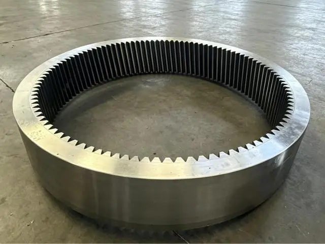
Understanding Internal Helical Gear Cutting: Principles and Processes
Internal Helical Gear Cutting tools make gears with angled teeth that are placed on the inside of cylinder housings. In contrast to external gears, where the teeth face outward, these parts mesh with pinions inside small areas, moving in the same direction and efficiently transferring power.
The Fundamental Cutting Process
The cutting process begins with material selection. 45# steel, 20CrMnTi, 40CrNiMo, and SAE4340 are utilized because they machine well and are strong after treatment. Coordinating our manufacturing phases is crucial. Initial teeth forms are rough-cut from raw material. It then undergoes semi-finishing to increase dimensional accuracy. Cooling or carburizing raises the surface hardness to 58–62 HRC, and teeth grinding creates ISO 6 Grade accuracy.
The math is challenging. The tool must move axially and rotationally for helix angles between 5° and 45°. Module sizes—0.5 to 50—determine tooling and feed rates. For smoother surfaces, bigger modules need more robust equipment and slower cutting rates.
Critical Parameters That Define Quality
Three factors largely decide the quality of the result. Cutting speed must strike a balance between productivity and tool longevity. Too fast of speeds create heat that warps workpieces, while too slow of speeds make cycle times longer than they need to be. The feed rate directly affects the surface finish. For example, smaller feeds make the sides smoother, but they take longer to machine. Tolerance management makes sure that involute profiles meet the design requirements. Deviations measured in microns change how the meshes fit together and the amount of noise they make.
Keeping an eye on the temperature during cutting is very important. When cutting tools rub against harder materials, friction causes localized melting that can cause the dimensions to shift. Effective coolant supply systems flush chips out of internal spaces while keeping temperatures stable. This stops residual stresses from building up and affecting how well the gear works when it's under load.
Common Machining Methods and Their Applications
There are four main methods used to make internal helical gears:
- By coordinating vertical strokes with circular indexing, reciprocating cuts form gear teeth. It works for tiny planetary carriers with blind apertures and shoulders near gear teeth. Average to lengthy cycle lengths depend on cell size and material hardness.
- Continuous monitoring and helical hobs enhance through-bore production automatically. Large two-to-eight-piece module orders with setup time covering tool cost work.
- Braaching single-stroke multi-tooth bars straightens Internal Helical Gear Cutting splines. Rotating broach systems handle limited-helix-angle helical profiles. This is less flexible than production.
- Grinding improves gear accuracy after strengthening. Heat-treated grinding wheels minimize distortion, provide surface finishes below Ra 0.8 µm, and correct pitch errors for quiet, accurate reducers.
- These strategies help numerous companies. After assessing their capabilities, procurement managers may pick the best procedures depending on batch amounts, tolerances, and budgets. We know from 15 years of production that project success depends on matching machining method to application.
Comparing Internal Helical Gear Cutting Methods: Making Informed Choices
To choose the best ways to do machining, you have to balance a lot of different priorities. Which technique is the best overall value depends on factors like cost, precision needs, and production volume.
Process Mechanics and Accuracy Comparison
The gear shape has several designs. Due to sluggish vertical cutter rotation, interrupted cuts and near features may be managed. Properly positioned equipment may meet DIN 5-7 quality criteria after cutting. Production may be dozens to hundreds of units.
Hobbing works with chipping. The hob spins quickly while feeding radially; thus, material loss is quicker than shaping. Work productivity increases after 500 units, and setup amortization justifies specialty fixtures. Good thermal stability and accuracy.
Fixing heat treatment defects requires more than cutting. Can grind. Heated items vary in size. Internal quenching pressures distort and expand the carburized casing. Grind flaws to restore design. This takes longer and costs more for near-perfect tooth contact.
New power skiving shapes and sharpens quickly. Continuous generation cycles various geometric shapes 3–5 times faster than traditional shaping. Traditional methods twisted the tool and workpiece revolutions, but CNC controls sync them.
Application Suitability and Cost Considerations
Fields value distinguishing qualities. Automotive transmission manufacturers with over 1,000 planetary ring gears may hire hobbing or skiving specialists to save expenses. Compact slewing drive rings from construction equipment manufacturers set up faster while costing more per piece. Still, aerospace manufacturers grind despite increasing blowback avoidance costs.
Purchase equipment with immediate and continuing expenses in mind. Pricey, accurate CNC gear form centers can do several tasks without changing. Automation reduces component prices on specialized hobbing lines but limits manufacturing changes.
Our CNC gear machining, automated grinding, and smart heat treatment lines are top-notch. We may provide job strategies due to our various options. Objective guidance that focuses on results helps clients.
Optimizing Gear Cutting Parameters for Precision and Efficiency
To get uniform quality across production runs, you need to carefully optimize the parameters. Setting up the tool so that it works with the material and gears properly affects the surface finish, the accuracy of the measurements, and how long the tool lasts.
Tailoring Settings to Gear Specifications
Module size greatly affects cutting. Milling fine-pitch gears with modules below 2 needs smaller cuts and quicker spinning rates to prevent teeth breaking. Carbide sharpens hundreds of cutters, while polished plugs save tool replacements. Both speed and surface quality are balanced at 0.05-0.15 mm/revolution.
Strong tools are needed to remove material from coarse-pitch gears with modules above 10. Cutting forces increase with tooth depth; therefore, machines must resist bending stress. 50–150 RPM spindle speeds and 0.3–0.5 mm/turn feed rates minimize cycle time and tool wear.
Huge helix angles impair chip escape and manufacturing. Tools become heavier at 30° angles because they increase cutting pathways and tangential pressure. Fast coolant delivery to the cutting zone is crucial. Flushing chips from the cutting zone and material holes before high-pressure chip finishing. Flood cooling is less effective than through-spindle coolers in difficult geometries.
Distinguishing Rough and Finishing Operations
Two-stage cutting improves efficiency and quality. Each roughing pass eliminates 1.5–3 mm of material fast. For speed, imperfect finishing is ok. Tools consume material faster than necessary to generate profiles within 0.1 to 0.2 mm of final measurements.
Final passes at moderate feeds and 0.2–0.5 mm cut depths polish the shape. To smooth flanks, reduced heat loads increase cutting speeds and tool engagement time per tooth. This approach corrects roughing-induced size discrepancies while maintaining surface roughness.
Heat is used between pre- and post-grinding. Carburizing or through-hardening hardens casings. Next, each side is ground off by 0.05-0.15 mm to remove distortion, restore precision, and achieve 58–62 HRC surface hardness. To avoid soft core crushing, consider case depth while removing stock.
Maintenance Practices That Extend Tool Life
Tool management impacts production costs. While more expensive, carbide gear shaper cutters may create hundreds of parts before needing to be reground. Normal flank wear checks prevent significant failures that harm workpieces and extend downtime.
Coolant quality impacts tool durability and smoothness. Lubrication is reduced by abrasive particles in contaminated fluids. Filtration and concentration monitoring keep cutting sharp, and machine-planned fluid changes are best.
Calibration standardizes machinery. Gear cutting machinery loses accuracy when ball screws wear out, and structural elements expand and compress. Annually, laser interferometry and precision artifacts verify placement. Before drift impacts product quality, standards are reset.
Procurement Guide: Selecting Internal Helical Gear Cutting Solutions
Structured assessment frameworks that compare capabilities objectively are helpful for manufacturers who are looking at outsourcing partners or new equipment investments.
Evaluating Manufacturers and Service Providers
Dependability is key to collaboration. On-time suppliers ease downstream assembly. ISO 6 Grade precision skills demonstrate technical ability, while ISO 9001 delivers peace of mind.
Innovation displays flexibility. Suppliers add power skiving, automated inspection, and digital process tracking. Precision CNC gear machining and fully automated grinding systems demonstrate our industrial innovation.
Great after-sales service sets suppliers apart. Planning using technical knowledge decreases manufacturability issues that increase costs and delays. Manufacturing communication helps plan and answer questions. Discussing needs, designing, building, testing, packaging, and shipping are typical steps. Project progress is essential for procurement managers.
Outsourcing Benefits and Quality Assurance
Businesses may train government agencies. Internal Helical Gear Cutting: Helical gear cutting requires expensive equipment, labor, and supervision. Use technologies that would take years to build in-house and establish flexible prices via outsourcing.
Demand is scalable and adaptable. Captive capacity idles when demand is low but restricts production when high. External partners change volume, allowing production growth without consumer investment. Small- and large-scale production are possible. One-piece prototypes and replacement parts are accepted.
Quality control safeguards purchasers against substandard items. Before delivery, size, finish, and surface hardness are checked. Quality control involves measuring tooth profiles, surface roughness, and case depth profile hardness using coordinate measurement equipment. A one-year guarantee shows you trust the job and lets you get your money back if difficulties develop.
Cost Analysis and Total Ownership Assessment
Consider the whole cost while purchasing. Poor quotations may indicate worse quality, longer lead times, or insufficient technical support, raising expenses. Well-known companies charge more for technical help, speedier shipment, and inventory management. Such services are cheaper.
Lead times impact working capital. Delivery shortcuts reduce inventory expenses and improve service. Delivery windows of 35–60 days combine manufacturing efficiency with client scheduling. We expedite urgent requests.
Transportation reliability completes value computation. Shipping degrades quality, costs money, and delays production. Wood pallets with shock-absorbing foam allow personalized packing with less than 0.1% shipping damage. Air, sea, and China-Europe freight trains may satisfy varied demands and timetables. Live shipment tracking is available from plant loading to customer delivery.
Building Trust: Why Partner with Industry-Leading Internal Helical Gear Cutting Providers
Long-term success in making gear transmissions depends on ties with suppliers that are based on trust and shared commitment.
Proven Track Records and Industry Reputation
Famous manufacturers develop reference portfolios to demonstrate their expertise. Long-term mechanical engineering relationships succeed. Industrial tools, mining equipment, and aerospace partnerships demonstrate our versatility in difficult fields.
Certifications guarantee third-party quality. ISO requires process documentation and growth frameworks. Industry-specific certificates demonstrate expertise. Industry expertise is shown by AS9100 aircraft and IATF 16949 automotive certifications.
Customer Support and Training Services
Tech assistance extends beyond bids and orders. Early project design guidance finds manufacturing difficulties before they cost money. Help picking materials balances cost and performance. Geometry optimization improves part manufacturing without losing utility.
Customers may learn using their own gear cutting tools. Suppliers should demonstrate machine operation, equipment selection, and setting optimization during installation and commissioning. Support keeps things working smoothly when users depart or new apps come out.
Plan drawings and professional coaching suit all pre-sales client demands. Quality check data and production progress sync. The guarantee and prompt issue resolution after delivery demonstrate responsibility.
Emerging Technologies and Future Trends
Innovations change production. Power skiving improves with machine control algorithms and cutter shape upgrades. This approach addresses the hobbing-shaping productivity gap and permits sophisticated interior geometry.
Rigid skiving avoids grinding. Advanced gearmaking machines with sturdy frames and carbide tools can cut steels exceeding 60 HRC in one step. Form-based adoption cycles save much.
Digital process monitoring improves quality. Real-time machine tool sensors measure sound, cutting forces, and temperature. Identify baseline disparities before problems arise to avoid scrap. Business operations improve with data-driven solutions.
The hybrid method combines additive and conventional cutting. Traditional technologies cannot make net-shaped gear blanks with cooling lines or weight-reducing mesh structures like metal 3D printing. Finish machining removes surface imperfections and preserves interior quality. Technology produces new designs.
Conclusion
For Internal Helical Gear Cutting to work, technical needs and business needs must be balanced. By learning about the basics of cutting, comparing different process options, and finding the best settings, you can make smart choices that always lead to precise results. Partnering with well-known suppliers who can show they know how to make things, are committed to quality assurance, and offer a wide range of support services can lower risks and give you access to capabilities that give you a competitive edge. Internal helical gears that are machined to exacting standards will continue to be essential parts in industrial, automotive, and aerospace applications even as transmission systems get more efficient and quieter.
FAQ
1. What distinguishes internal helical gear cutting from external gear machining?
Internal gears have teeth on the inside that mesh with pinions on the outside, both turning in the same direction. This setup makes small units with better contact ratios that lower noise. The complexity of machining goes up because tools are harder to get to and chips are harder to get out of small cavities.
2. How do cost and precision trade-offs affect supplier selection?
For low-noise uses, grinding processes are needed for higher precision, but they cost more. Check to see if your application really needs ISO 6 Grade accuracy or if ISO 7-8 will do the job for less money. Reliable suppliers help match specifications to functional needs instead of giving too many details that aren't needed.
3. What quality assurance practices should buyers expect from suppliers?
Coordinate measuring tools should be used to check the tooth profile geometry, profilometry should be used to check the surface finish, and comprehensive inspection methods should check the hardness across case depths. For parts that are supplied, ask for inspection reports and make sure that buy orders have clear criteria for what can be accepted. As part of our quality control measures, we check all the dimensions of every item before sending it out, and we back this up with a one-year warranty.
4. Can small batch orders achieve competitive pricing?
Specialized makers with flexible CNC systems can make small amounts of goods at a low cost by cutting down on setup times. We don't require big batch amortization because we can make one-piece pieces or low-volume orders. Instead, we balance efficiency through process improvement.
Partner With YIZHI MACHINERY for Expert Internal Helical Gear Manufacturing
When it comes to making high-quality internal helical gears, YIZHI MACHINERY has been doing it for fifteen years. We can do everything from choosing the right materials to inspecting the finished products. We can make parts out of 45# steel, 20CrMnTi, 40CrNiMo, and other unique metals that meet ISO 6 Grade standards. We can work with modules ranging from 0.5 to 50, helix angles of 5° to 45°, and surface hardness requirements of 58–62 HRC, which we can meet with modern heat treatment methods. As a supplier with a lot of experience in Internal Helical Gear Cutting, we can make any changes you want and deliver quickly (35 to 60 days), all while protecting your order in a way that keeps damage rates below 0.1%. Contact us at sales@yizmachinery.com to talk about your needs for transmission parts and get thorough specs that are made just for your purpose.
References
1. Stadtfeld, H.J. (2014). Gear Cutting and Grinding Processes: Principles and Applications. Gleason Corporation Technical Publications.
2. Radzevich, S.P. (2017). Theory of Gearing: Kinematics, Geometry, and Synthesis. CRC Press, Boca Raton, FL.
3. Klocke, F., Brecher, C. (2016). Gear Manufacturing Technology: Processes, Machines, and Tools. RWTH Aachen University Institute for Machine Tools and Production Engineering.
4. ISO 1328-1:2013. Cylindrical Gears - ISO System of Flank Tolerance Classification. International Organization for Standardization.
5. Davis, J.R. (2005). Gear Materials, Properties, and Manufacture. ASM International, Materials Park, OH.
6. Litvin, F.L., Fuentes, A. (2004). Gear Geometry and Applied Theory. Cambridge University Press, Cambridge, UK.

USER EVALUATE
Here is the customer's evaluation of us