


Internal Helical Gear Buyer's Guide: How to Select the Right Industrial Gear
To pick the right Internal Helical Gear, consider design, functioning, and supplier expertise. These precision-engineered pieces feature angled cylinder ring teeth. They make tiny, high-torque transmissions for winches, machine tool feed systems, and planetary gear reducers. For industrial tools, mining, and aviation, your purchase influences its performance, cost, and longevity. This handbook covers material parameters, helix angles, manufacturing procedures, and supplier evaluation. This will help you make wise technical and budget-friendly purchases.
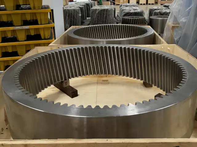
Understanding Internal Helical Gears: Design, Function, and Advantages
Internal Helical Gears feature teeth machined into a cylinder's inner surface at an angle to the gear axis. Unlike external gears with outward-facing teeth, internal configurations create concave meshing surfaces wrapping around matching pinions. This fundamental design difference delivers significant operational advantages that address common industry challenges across mining, aerospace, and industrial machinery applications.
The Engineering Behind Helical Tooth Geometry
Helix angles between 5° and 45° enable gradual tooth engagement rather than instantaneous contact. Engagement starts at one tooth end, progressively spreading across the face, distributing loads and reducing impact forces. This progressive engagement directly addresses high-speed transmission noise and vibration issues. Smooth load transfer along tooth flanks provides advantages in applications with strict noise, vibration, and harshness requirements like planetary gear reducers and aircraft systems.
Operational Mechanics and Load Distribution
Internal Helical Gears achieve 20-30% higher torque density within same envelope dimensions through concave-convex meshing relationships. Contact ratios exceed spur versions with multiple teeth engaged simultaneously, reducing localized stress concentrations. This load-sharing capability proves especially valuable in mining equipment and heavy machinery with shock loads and varying force levels. Improved stress distribution directly translates to extended service life and reduced maintenance requirements.
Compact Design Benefits for Space-Critical Applications
Internal configurations naturally allow shorter centre distances than external setups. Ring-and-pinion architecture enables component nesting within compact envelopes, valuable for machine tool spindle housings and compact winch systems. Surrounding ring structure provides robust support while maintaining small footprint. This compactness proves particularly valuable in aerospace applications where weight and volume constraints dominate. High reduction ratios within confined spaces make these gears ideal for actuator systems and landing gear mechanisms.
Comparing Internal Helical Gears with Other Gear Types: Making the Right Choice
Understanding how different gear configurations meet operational requirements ensures optimal selection. Internal Helical Gears occupy a unique performance space with distinct advantages for specific applications.
Internal Helical vs. Internal Spur Gears
Spur gears with straight teeth parallel to the gear axis offer simpler manufacturing but inferior performance. Sudden tooth engagement in spur designs generates more noise and vibration, particularly at higher speeds. Helical designs typically reduce transmission noise by 6-10 decibels under equivalent loads. Larger contact areas reduce surface pressure, lowering pitting and scoring risk. Continuous heavy-load applications like mining conveyors benefit significantly from this increased durability, though helical designs require thrust bearings to handle axial forces.
Comparison with External Helical Gears
External helical gears place teeth on the outside circumference, altering load transmission and spatial arrangement. Internal configurations consistently deliver higher torque capacity within equivalent envelope dimensions due to enclosing mesh geometry. Concave-convex tooth contact in internal arrangements provides superior load paths versus convex-convex external gear contact. Internal sets achieve similar reduction ratios while occupying substantially less overall space, making them superior for planetary gear reducers where multiple pinions rotate around a central sun gear within a fixed internal ring gear.
Performance Against Bevel and Worm Gear Alternatives
Bevel gears transmit motion across crossing shafts at right angles, unlike parallel-shaft internal helical systems. When shaft orientation requires right-angle power transfer, use bevel gears. Internal Helical Gears improve efficiency and load capacity in parallel-shaft applications that need strong torque in small spaces. Worm gear sets have high single-stage reduction ratios and self-locking, however they are 50-70% efficient compared to 95-98% for helical arrangements. Due to heat from sliding, worm meshes need specific lubricants.
Critical Selection Criteria Framework
When deciding between gear types, consider these essential factors.
1. Torque Capacity and Load Characteristics: Internal Helical Gears are superior in continuous-duty, high-torque applications that experience intermittent shock loads typical in mobile equipment and industrial machinery. Multi-tooth engagement adeptly manages transient overloads.
2. Noise and Vibration Tolerance: Machine tool feed systems that need accurate placement require smooth engagement from helical tooth shape. Noise suppression is very useful in workplaces with safety and comfort rules.
3. Space Constraints: Compact housing makes internal helical designs appealing. Due to their higher reduction ratios, planetary reducer systems need bigger housings with external gear arrangements.
4. Efficiency: Helical gears save energy and heat by 95-98% each stage compared to worm gears. This trait is crucial for battery-powered equipment and applications with heat control issues.
Procurement Insights: Sourcing and Buying Internal Helical Gears for Industrial Applications
Successful procurement requires understanding global supply chains, manufacturing capabilities, and supplier evaluation aligned with technical requirements.
Global Manufacturing Landscape and Sourcing Options
China has become a prominent center for precision gear manufacture, equipped with powerful CNC machining centers, automated grinding machines, and sophisticated heat treatment systems. Established Chinese exporters catering to worldwide markets spend substantially in quality control systems and ISO certification. Companies such as YIZHI MACHINERY, established in 2016 and with 15 years of production expertise, demonstrate the progress of high-precision manufacturing. International sourcing choices must assess the overall cost of ownership, including freight, customs, communication efficacy, and after-sales technical assistance.
Understanding Cost Drivers and Pricing Dynamics
The choice of material greatly influences cost—premium alloy steels such as 20CrMnTi are more expensive than conventional 45# steel because of their enhanced mechanical qualities and heat treatment performance. The decision of precision grade affects cost, since ISO Grade 5-6 necessitates more grinding and more stringent quality control compared to commercial grades. Customization directly influences expense and delivery duration. Standard catalog goods provide expedited delivery and reduced unit prices via economies of scale. Custom-engineered gears requiring precise modules, helix angles, or tooth grinding specifications need further engineering and specialized manufacturing arrangements. Volume concerns influence price via economies of scale for extensive manufacturing runs.
Evaluating Supplier Technical Capabilities
The competence of the manufacturing process dictates the attainment of specifications. The manufacturing of internal helical gears often utilizes gear shaping or power skiving, with power skiving providing cycle durations that are three to five times quicker and enhanced surface finishes. Heat treatment capabilities need meticulous assessment. Surface hardness varies from 45-50 HRC to 58-62 HRC according on application specifications, with increased hardness providing enhanced wear resistance in challenging conditions. The ability to grind teeth differentiates precision gear makers from typical machine shops, ensuring the surface smoothness and dimensional accuracy required for ISO Grade 5-6 precision.
Warranty Terms and After-Sales Support
Extensive warranty coverage reflects the supplier's confidence in product quality. Standard industry warranties generally include material faults and manufacturing problems for one year after delivery. Comprehend warranty stipulations about normal wear as opposed to premature breakdown and the associated claim processes. Technical support beyond warranty provisions. Suppliers providing pre-sales engineering support enhance gear specification to meet application needs. Updates on production status and documentation of quality inspections provide transparency throughout manufacturing. Post-delivery support, including troubleshooting advice and availability to replacement parts, guarantees sustained operational performance.
Lead Time Planning and Logistics Considerations
Custom internal helical gears often need a production timeframe of 35 to 60 days, contingent upon complexity, manufacturing capacity, and material availability. This timetable includes material acquisition, cutting, heat treatment, finishing, quality inspection, and packing. Expedited orders may be offered at an elevated cost. The logistics infrastructure profoundly influences the success of international procurement. Dependable providers orchestrate maritime, aerial, and international rail logistics, determining the most efficient mode of shipment according to order volume and urgency. Real-time tracking offers visibility of shipments throughout transit. Custom hardwood containers equipped with shock-absorbing liners safeguard fragile tooth surfaces during transit.
Maintenance, Troubleshooting, and Longevity of Internal Helical Gears
Proactive maintenance, systematic inspection routines, and prompt response to developing problems maximise service life before costly failures occur.
Lubrication Practices and Fluid Selection
Effective lubrication establishes a protective barrier between metal surfaces, reduces friction, and absorbs heat created by meshing. Internal helical gears have considerable sliding contact owing to the helix angle, making lubricant selection essential. GL-5 grade gear oils with severe pressure additives are appropriate for high-load or shock-load applications. The selection of viscosity must correspond to the operational temperature ranges and rotating rates. Fluids with increased viscosity provide denser protective layers, although they elevate operating temperatures and churning losses. Fluids with lower viscosity decrease friction but may fail to sustain sufficient film thickness under substantial loads. Synthetic lubricants provide enhanced performance across wider temperature ranges and exhibit improved oxidation resistance.
Inspection Protocols and Early Failure Detection
Routine visual examinations detect emerging issues prior to their escalation. Observe for oil loss signifying seal degradation, atypical noise indicating bearing or alignment problems, and heightened vibration suggesting tooth damage or imbalance. Thermal imaging detects anomalous heat patterns that indicate lubrication issues or excessive friction. Predictive maintenance systems provide condition-based service. Vibration analysis detects distinct failure modes via distinctive frequency patterns. Ultrasonic testing identifies nascent bearing issues and lubricant inadequacies promptly. Wear particle analysis reveals causes of component deterioration for focused intervention.
Common Issues and Troubleshooting Strategies
- Excessive Noise Development: Increasing operational noise typically indicates inadequate lubrication, abrasive contaminants, or progressive tooth damage. Check lubricant level and condition, verify correct viscosity grade for operating conditions, and inspect for water or particulate contamination. Even with apparently satisfactory lubricant, close inspection may reveal micropitting or early macropitting requiring component replacement.
- Unexplained Efficiency Loss: Declining transmission efficiency manifests as increased power consumption or reduced output performance. Causes include inadequate lubrication causing excessive friction, bearing wear increasing parasitic losses, or seal failure causing oil loss. Temperature monitoring often identifies the component section generating excess heat, focusing diagnostic efforts.
- Vibration and Balance Issues: Unusual or increased vibration often results from imbalance, misalignment, or damaged components. Verify shaft alignment meets specifications, check mounting bolt torque, and inspect coupling condition. If mechanical factors appear satisfactory, internal tooth or bearing damage may require disassembly and detailed inspection.
Material Selection Impact on Durability
Material specification significantly influences gear performance and longevity. Premium alloy steels including 20CrMnTi, AISI 8620, and 42CrMo provide superior strength, wear resistance, and heat treatment response compared to basic carbon steels. These materials handle contact pressures and dynamic loading more effectively in demanding applications. Heat treatment creates optimised surface hardness profiles balancing wear resistance with core toughness. Carburising delivers hard, wear-resistant surfaces at 58-62 HRC with tough, impact-resistant cores. Quenching and tempering provide uniform properties throughout the cross-section. Induction hardening selectively hardens tooth surfaces while maintaining softer gear body.
Final Considerations and How to Make the Best Purchasing Decision?
Successful procurement translates technical requirements into purchasing outcomes through systematic supplier evaluation, clear specification communication, and alignment of performance needs with budget realities.
Aligning Specifications with Application Demands
Commence with a comprehensive evaluation of application requirements. Specify operational velocities, duty cycles, transmitted energy, and environmental parameters. These factors dictate the necessary load capacity, precise classifications, material requirements, and heat treatment procedures. Insufficient specification results in early failure and expensive downtime. Over-specification expends resources on superfluous accuracy or materials. Account for future needs throughout the specification process. Conservative design margins enhance applications anticipated to experience heightened loads or prolonged duty cycles. Commercial tolerances may be enough for prototypes or small-scale manufacturing, hence minimizing upfront expenditure.
Comprehensive Supplier Evaluation Framework
Price comparison is just one aspect of supplier assessment. Evaluate manufacturing capabilities, including equipment sophistication, quality control systems, and certification status. ISO-certified facilities exhibit a dedication to systematic quality management. Assess the accessibility of technical support throughout the procurement process. Pre-sale engineering support aids in refining specs and preventing expensive mistakes. Updates on production progress and inspection notifications sustain trust throughout the manufacturing process. Post-delivery support, including warranty coverage and troubleshooting help, safeguards your investment. Evaluate the efficacy of communication and the degree of receptivity. Lucid and prompt communication mitigates misconceptions and expedites problem resolution.
Risk Mitigation and Quality Assurance
Solicit complete quality paperwork, including material certificates, dimensional inspection reports, and heat treatment records. Reputable suppliers provide comprehensive traceability that verifies compliance with specifications. Evaluate first-article inspection for essential applications or new supplier partnerships. FAI rigorously evaluates first production units prior to full-scale production, ensuring that manufacturing procedures provide compliant components. Define explicit inspection criteria and acceptance requirements. Specify essential dimensions necessitating inbound inspection, establish sample schedules for production volumes, and outline actions for nonconforming materials. Written contracts mitigate conflicts and guarantee responsibility.
Conclusion
When choosing the right Internal Helical Gear, you have to weigh technical specs, provider skills, and cost. By understanding basic design concepts like spiral angles, load distribution characteristics, and material qualities, you can make smart choices about which components to use in different situations. By comparing gear types, it's easier to see when internal helix designs are better than other technologies. A full review of a supplier looks at more than just price. It also looks at the seller's manufacturing skills, quality systems, and support services. Regular upkeep and organized fixing make things last longer, which increases the return on investment. For buying to go well, these parts need to be put together in a way that makes sense and fits within the budget. This way, standards can be met while still working well in tough industrial settings.
FAQ
1. How Do Material Choices Impact Internal Helical Gear Performance?
Internal Helical Gear performance, load capacity, wear resistance, and lifetime depend on material choice. Premium alloy steels like 20CrMnTi and AISI 8620 outperform carbon steels in strength and heat treatment. Carburizing at 58-62 HRC produces wear-resistant surfaces with impact-resistant cores. Demanding applications benefit from premium materials and heat treatment for longer service life and less downtime.
2. What Techniques Minimize Noise and Backlash in Helical Gear Systems?
Selecting a helix angle of 15-30 degrees allows progressive tooth engagement and reduces noise. Transmission mistake causes vibration and noise. ISO 5–6 accuracy grades mitigate this. Grinding teeth produces the surface polish needed for silent operation. Proper viscosity fluid lubrication reduces vibration and metal-to-metal noise. Precision manufacturing tolerances and center distance assembly are needed to control backlash. Precision machine tool feed mechanisms are protected from accuracy loss by regular wear testing before backlash.
3. What Factors Influence Lead Times for Custom Gear Orders?
Complexity of production greatly impacts delivery timeframes. Custom designs that need new cutters or fixtures arrive slower than regular standards manufactured using existing gear. Common alloys are easily available, while unusual materials must be ordered. Time-sensitive needs benefit from advance scheduling due to manufacturing capacity and order backlogs. Heat treatment and grinding take longer but are necessary for precise applications. Standard custom internal helical gear manufacture takes 35-60 days, including engineering, machining, heat treatment, finishing, inspection, and logistics.
Partner with YIZHI MACHINERY for Precision Internal Helical Gear Solutions
YIZHI MACHINERY has been making handmade Internal Helical Gears for 15 years and has quality systems that are in line with ISO standards. Our high-tech CNC lathes, precise cutting tools, and full range of heat treatment options allow us to make gears that meet ISO Grade 5-6 standards for module ranges from 0.5 to 50. We use high-quality materials like 20CrMnTi, AISI 8620, and 42CrMo to make our products. The surface hardness ranges from 45 to 50 HRC to 58 to 62 HRC, depending on what your application needs. Our streamlined customization process includes requirement gathering, design, production, inspection, and transportation. This ensures delivery in 35 to 60 days and lets you see real-time progress. We are an experienced Internal Helical Gear supplier that works with industries like mining, aircraft, and industrial machinery around the world. Our minimum order amounts are flexible, and we can even make a single piece. Contact us at sales@yizmachinery.com to talk about your needs and get detailed quotes along with full expert help.
References
1. American Gear Manufacturers Association. (2015). AGMA 2015-1-A01: Accuracy Classification System - Tangential Measurements for Cylindrical Gears. Alexandria, VA: AGMA Publications.
2. Budynas, R.G., & Nisbett, J.K. (2020). Shigley's Mechanical Engineering Design (11th ed.). New York: McGraw-Hill Education.
3. International Organization for Standardization. (2013). ISO 1328-1:2013: Cylindrical Gears - ISO System of Flank Tolerance Classification. Geneva: ISO Publications.
4. Dudley, D.W. (1994). Handbook of Practical Gear Design and Manufacture. Boca Raton: CRC Press.
5. Radzevich, S.P. (2016). Dudley's Handbook of Practical Gear Design and Manufacture (3rd ed.). Boca Raton: CRC Press.
6. Stadtfeld, H.J. (2014). Gleason Bevel Gear Technology: The Science of Gear Engineering and Modern Manufacturing Methods for Angular Transmissions. Rochester: The Gleason Works.

USER EVALUATE
Here is the customer's evaluation of us