


How to choose the right gear wheel shaft for industrial machinery
It's very important to pick the right gearbox part for your production line. When we choose a Gear Wheel Shaft for a conveyor belt, a food packaging line, or farm equipment, we're making a choice that has a direct effect on the equipment's uptime, upkeep costs, and total performance. A Gear Wheel Shaft is an integral gearbox part where the gear teeth and shaft body are machined to be one piece, so there are no weak spots like keyways that can happen with other types of assemblies. When you're on a tight production plan with little time for breaks, this combination gives you better torque density, structure stiffness, and vibration reduction.
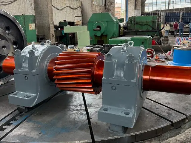
Understanding Gear Wheel Shafts and Their Functions
What Defines a Gear Wheel Shaft?
A Gear Wheel Shaft is very different from regular designs, where separate gears are attached to shafts with keys or splines. This incorporated method cuts the shape of the gears directly into the shaft material, making a single piece that transfers torque and rotational motion without any weak spots caused by assembly. The seamless construction solves long-standing problems in the industry, like concentricity errors that cause bearings to fail early, fretting corrosion at contact surfaces, and backlash from built-up tolerances.
We can see this part working with input speeds of up to 15,000 RPM in small gears while staying quiet, which is very important when noise limits get stricter and comfort at work is important. The design gets rid of places where stress builds up and fatigue cracks start, which makes the service life longer than what multi-piece assemblies can do.
How Gear Wheel Shafts Differ from Related Components
Understanding the differences helps buying teams make the right requests. Axles mostly support weight without sending power, and drive shafts connect parts that are far apart but don't usually have gear teeth. Transmission shafts can have gears mounted on them separately, which causes tolerance stack-ups that Gear Wheel Shafts get rid of. This level of detail is important when looking through seller catalogues or talking about custom requirements, because getting the types of parts wrong can cause expensive mistakes in specifications and project delays.
Common Types and Their Material Considerations
The manufacturing landscape has a number of configurations that can be used for different purposes:
1. Solid Construction: These have the highest torsional rigidity for handling heavy shock loads in cement mills or mining crushers. The continuous cross-section stops bending deformation that would throw off the alignment of matching gears, keeping the tooth contact patterns even when the load changes. Forging from alloy steels like 42CrMo (AISI 4140) or 20CrMnTi is usually used in manufacturing. This gives the material the volume it needs for later heat treatment processes.
2. Hollow Designs: Robotics and aircraft use them to save weight because every kilogram changes how much energy they use or how much they can carry. The tube shape keeps the right amount of rotational stiffness while reducing mass by 30–40% compared to solid alternatives. Higher-strength alloys like SAE 4340 or 18CrNiMo7 are chosen as materials to make up for the smaller cross-sectional area.
3. Keyed Variants: Some designs have continuous gear teeth, but they also keep keyways at the coupling ends to give you more options for how to join. This mixed method works well for retrofit projects where the interfaces between old and new equipment need to stay the same.
4. Splined Configurations: Spline terminations are useful for applications that need to be able to change the axial length or that need to take parts apart often. When compared to single-key links, the multiple contact teeth spread out the torque loads, which makes them last longer.
The limits of performance are largely set by the choice of materials. High-grade alloy steels find the right balance between tensile strength and flexibility. This is an important trade-off when parts need to handle shock loads without breaking easily. As a result of the carburising heat treatment, the top layers become HRC 58–62 hard, which makes them resistant to wear, while the cores stay HRC 30-45 tough. This gradient structure is like the way bones are naturally made, so it makes parts that don't wear down easily on the outside but can handle impact loads.
Design Principles Governing Performance
When figuring out a load's capacity, you have to take into account all of its stresses, including axial thrust in helical gear uses, torsional shear from transferred torque, and bending moments from gear separation forces. Tolerances in manufacturing have a direct effect on these figures. For example, precision grinding to ISO 6 Grade makes sure that tooth profiles keep their design shape under load, which stops premature pitting or scuffing failures.
Precision in fit goes beyond the gear teeth themselves. To keep press fits from coming loose over time, fretting corrosion in bearing journals needs tight diameter tolerances and a smooth surface (usually Ra < 0.8µm). To keep dynamic instability and vibration problems that speed up bearing wear to a minimum, the geometric relationship between the bearing seats and the gear centerlines must stay within microns of being concentricity.
Criteria for Selecting the Right Gear Wheel Shaft
Evaluating Operational Requirements
The duty cycle of your machinery determines the specifications of its parts. Packaging machines go through thousands of start-stop cycles every day, which is very different from conveyor systems that run at steady speeds all the time. When it comes to farming equipment, shock loads—like when stones hit gathering equipment—need higher safety standards than smooth industrial automation applications.
Extreme temperatures change the qualities of materials and make lubricant less effective. In just one shift, the temperatures of food preparation equipment may go from being cold for chilling to being hot for steam sanitisation. Corrosion exposure is just as important. In coastal marine settings or chemical processing plants, where regular carbon steels would break quickly, you have to use stainless metals or special coatings.
Material Selection and Surface Treatment Strategies
We use a variety of alloy steels to make Gear Wheel Shafts, and each one is best for a certain range of performance. The range of materials includes 45# steel for general-purpose uses, 20CrMnTi for carburising to make cases that are deeply hardened, and 40CrNiMo for through-hardening to make big parts with consistent properties. SAE 4340 is best for aircraft applications that need high strength-to-weight ratios, while AISI 8620 works great for carburised gearbox applications.
Surface processes change what a base material can do. Before quenching, carburising spreads carbon into the surface layers. This makes cases up to 2 mm deep that don't wear down and tough cores that don't change. Through-hardening in smaller parts is achieved by quenching and tempering. This gives the metal uniform qualities that are good for mild loads. When induction hardening is done, it only affects the bearing journals or gear teeth. This leaves the shaft bodies soft so that they are easy to machine.
The choice strikes a mix between cost and effectiveness. Through-hardening lowers the chance of distortion during heat treatment, but it may lower the hardness of the surface. Carburising makes the contact fatigue resistance better, but it needs to be ground down afterward to restore precision, which takes more time and costs more money. These trade-offs have to be weighed by procurement teams against performance goals and spending limits.
Dimensional Accuracy and Fitment Verification
Accurate measurements keep expensive installation problems from happening. It is necessary to make a difference between nominal, minimum, and maximum values for diameter specifications. Tolerance bands for bearing journals usually run from h6 to h7, and tighter specifications raise the cost of production. When measuring length, it's important to take into account how much the material will expand when it's used, especially for long shafts that span more than one bearing support.
Standardised measures say that keyway sizes should be the same as shaft diameters, but special equipment may not follow these rules. A common problem with keeping old machines is that measuring worn-out parts often shows original sizes that aren't shown in the paperwork. Helix angles in helical gears affect thrust loads and the choice of bearings, so it is important to get accurate angular measurements when making specifications.
Ensuring Component Compatibility
Interface standards must be followed for integration to work well. The hole sizes, shoulder heights, and fillet radii of chosen rolling element bearings must match. Gear mesh needs modules, pressure angles, and helix angles that are all the same between parts that are meant to fit together. Even small things like chamfer sizes can change how easy it is to put something together and how stress is distributed.
Custom solutions are sometimes cheaper than pushing standard parts into situations where they don't work. We've solved many problems where small changes to the dimensions got rid of the need for expensive adapter hardware or new housing designs. The ability to change tooth counts, face widths, or shaft extensions often lowers the overall cost of the system, even if some parts cost more.
Comparing Gear Wheel Shafts: Making an Informed Decision
Understanding Functional Distinctions
Gear Wheel Shafts are part of larger gearbox sets and do specific jobs. Instead of just moving rotation from one point to another, like simple gearbox shafts do, these parts actively slow down or increase torque through their built-in gear geometry. When used in cars, drive shafts prioritise rotational freedom through universal joints, while Gear Wheel Shafts focus on precise tooth contact and load capacity.
Knowing these differences keeps you from applying them in the wrong way. A gearbox shaft might be able to handle the same amount of torque, but its surfaces aren't precisely ground and hardened like gear teeth' need to be. When you replace parts without knowing how they work differently, you can speed up wear or cause catastrophic breakdowns.
Load Capacity Analysis and Safety Factors
There are several failure modes that go into figuring out the right load capacity. Contact stress between gear teeth that are mated leads to subsurface fatigue, which in turn leads to pitting, which is the microscopic removal of material that makes surfaces rougher and increases friction. Stress that causes bending at the roots of teeth can start cracks that spread and lead to a severe tooth fracture. Torsional shear can be stronger than the yield strength of some shaft parts when they are overloaded.
There is some uncertainty in estimating the load, and the properties of materials can change over time. Safety factors take these things into account. In the business world, it is common to use factors of 1.5 to 2.0 for smooth loads and 2.5 or higher for shock loads. These multipliers have a direct effect on the size and cost of the component. Specifications that are too strict waste money and space, while factors that are too low risk failures and production losses.
Evaluating Supplier Capabilities and Reputation
Industrial gearbox suppliers range from global brands (e.g., SKF, Timken) offering reliable standardized products and strong engineering support, to mid-tier specialists balancing cost and lead time, and custom machine shops suited for prototypes but with limited certification capacity. Supplier evaluation includes ISO 9001 certification, customer references, and OEM experience. Our 15-year partnerships and advanced CNC and grinding systems ensure consistent precision and quality performance.
Procuring Gear Wheel Shafts: From Inquiry to Purchase
Sourcing Options and Channel Selection
Modern procurement, digital sourcing tools are used along with standard wholesale ties. Established suppliers offer relationship benefits, such as expert advice during the planning phase, the ability to quickly replace items that are out of stock, and the ability to organise shipping schedules. Online industrial marketplaces make prices clear and give you access to suppliers from around the world, but they may not offer engineering support or quality assurance.
Custom machining services are useful for one-of-a-kind tasks that can't be found in standard catalogues. This method works especially well for changing equipment, increasing its capacity, or replacing old parts when the original maker no longer supports older equipment. The customisation process usually takes 35 to 60 days, based on how complicated it is and how busy the shop is. It starts with communicating the needs and ends with production cutting for a new Gear Wheel Shaft.
Understanding Pricing Structures
Quotes are affected by more than just the cost of raw materials. The level of precision needed has a huge impact on the cost of production. For example, to get ISO 6 Grade accuracy, more grinding processes and quality inspection time are needed than for rougher market grades. Customisation requires more engineering hours to confirm the design and often needs special tools that spread fixed costs over a larger order.
Costs are affected by heat treatment methods in a big way. For carburising, the metal needs to be heated for a long time in a controlled atmosphere. After that, it needs to be quenched, which requires careful temperature control to keep it from warping or breaking. More money has to be spent on grinding to recover precision after heat treatment damage. Choosing the right material also affects the price. For example, exotic alloys like AISI 4340 or 18CrNiMo7 are much more expensive than standard carbon steels even though they work better.
Volume discounts are based on economies of scale in setup time and the wear and tear on tools. We accept low minimum order amounts and can even make a single item if concept testing or an emergency replacement needs to be done right away. Small and medium-sized makers whose order patterns don't allow them to buy in bulk can benefit from this freedom.
Strategic Supplier Engagement
Effective procurement requires clear and detailed specifications, including dimensions, materials, hardness, and application requirements, to reduce misunderstandings and enable optimized supplier proposals. Buyers should evaluate lead times, certifications, and after-sales support such as warranties, returns, and response speed. Logistics also play a key role, with protective packaging and multiple transport options (sea, air, rail) plus real-time tracking to ensure safe, reliable, and transparent delivery planning.
Maintenance and Troubleshooting of Gear Wheel Shafts
Establishing Preventive Maintenance Protocols
Schedules for proactive inspections find problems as they arise, before they become so bad that they stop production. Visual inspection during regular lubrication intervals shows early warning signs like uneven wear patterns that mean the bearings aren't lined up right, discolouration that means the bearings are getting too hot, or surface cracks that mean the bearings are wearing out faster than expected. Maintenance teams look at characteristic frequency patterns that are picked up by vibration tracking to find problems with gear mesh or worn bearings for every Gear Wheel Shaft in service.
Identifying and Resolving Common Issues
Misalignment is a common field issue, causing uneven load distribution, edge stress concentration, and higher operating temperatures; it is corrected through precise measurement, shimming, or housing adjustments. Corrosion occurs due to environmental exposure, moisture, or chemicals, leading to pitting and fatigue, and is mitigated with corrosion-resistant materials and protective coatings. Surface damage from impact or improper handling reduces performance and may require repair or replacement depending on severity.
Making Repair or Replacement Decisions
Repair or replacement decisions are based on cost–benefit analysis between repair costs, replacement costs, and downtime risk. Minor wear or localized tooth damage may be repaired through grinding if production disruption is high, though with reduced load capacity. However, cracks or severe wear require full replacement due to safety risks and structural weakness. A one-year warranty and technical support help guide correct maintenance decisions.
Conclusion
To choose the right Gear Wheel Shaft, you have to weigh the technical specs against the needs of the operation and your budget. We've talked about how integral construction gets rid of assembly flaws, how choosing the right material and heat treating it set the limits of performance, and how precision manufacturing makes power transmission reliable. Knowing the differences between component types can help you avoid costly mistakes when using them, and carefully checking out suppliers can help you get the quality and support you need for your business. Regular care increases the useful life of an item, and smart choices about whether to repair or replace it lower the overall cost over its lifetime. With this information, procurement workers and design experts can choose parts that make machines more reliable, cut down on unplanned downtime, and make equipment work better overall in their industrial settings.
FAQ
1.What differentiates a gear wheel shaft from a standard transmission shaft?
A Gear Wheel Shaft has gear teeth that are cut into the body of the shaft, making it a single piece that transfers power through mesh contact. Standard gearbox shafts don't have gears built in. Instead, they use keys or splines to attach different gear components. This combination gets rid of assembly flaws and weak spots, making it possible to get better concentricity and torque capacity in smaller spaces.
2.How do I accurately measure dimensions for gear wheel shaft replacement?
Using precision micrometres, measure the diameters of the shafts at the bearing journals and record the readings at several points to find wear taper. Use callipers to measure the total length between the shoulders or ends, taking into account any changes in size caused by wear. To figure out the module for gear sections, you need to count the teeth and measure across several teeth. Use special measuring tools to write down the keyway's width, depth, and length. Photographs with scale marks help sellers understand complicated shapes when they are quoting.
3.Which materials work best for heavy-duty industrial applications?
Heavy-duty uses that need high strength and toughness should use alloy steels like 42CrMo, 40CrNiMo, or SAE 4340. Carburising grades like 20CrMnTi or AISI 8620 give surfaces that are very hard after heat treatment while keeping cores that are flexible and can handle shock loads. To choose the right material, you should think about both the amount of ongoing load and any sudden impacts that might happen. The material should also be able to handle heat treatment to reach a goal surface hardness of HRC 58–62 and a core toughness of HRC 30–45.
Partner with YIZHI MACHINERY for Precision Gear Wheel Shaft Solutions
YIZHI MACHINERY makes custom gearbox parts for small and medium-sized equipment makers that work in the fields of farming equipment, conveyor systems, and packing machinery. Our Gear Wheel Shaft provider can provide a wide range of materials, from 45# steel to SAE 4340, as well as modern heat treatment methods that achieve a surface hardness of HRC 58–62 and precise grinding to ISO 6 Grade standards. With 15 years of production experience and delivery times of 35 to 60 days, we've formed partnerships with many OEMs that want reliable parts backed by technical support and a one-year warranty. Our customisation process, which includes communicating your needs, making design plans, inspecting for quality, and transporting the parts safely, makes sure that they meet your exact requirements. Contact us at sales@yizmachinery.com to talk about your application needs and get thorough technical plans that are made to fit the needs of your machinery.
References
1. Budynas, R. G., & Nisbett, J. K. (2020). Shigley's Mechanical Engineering Design (11th ed.). McGraw-Hill Education.
2. Deutschman, A. D., Michels, W. J., & Wilson, C. E. (2018). Machine Design: Theory and Practice (2nd ed.). Macmillan Publishing.
3. Dudley, D. W. (2019). Handbook of Practical Gear Design and Manufacture (3rd ed.). CRC Press.
4. ISO 1328-1:2013. Cylindrical Gears — ISO System of Flank Tolerance Classification.
5. Maitra, G. M. (2017). Handbook of Gear Design (2nd ed.). Tata McGraw-Hill Publishing.
6. Norton, R. L. (2019). Machine Design: An Integrated Approach (6th ed.). Pearson Education.

USER EVALUATE
Here is the customer's evaluation of us