


Large Worm Gears: How to Maximize Potential in Application
Understanding how Large Worm Gear systems can deliver exceptional torque multiplication in compact configurations is the first step to getting the most out of them. When it comes to industrial machinery, mining operations, and aircraft ground support equipment, where reliable power transfer under big loads is key to success, these heavy-duty gearbox parts are the best. When engineering teams choose the right materials, follow strict maintenance procedures, and work with experienced manufacturers, they can improve performance. This leads to less downtime, longer equipment life, and measurable cost savings in tough production environments.
Understanding Large Worm Gears: Fundamentals and Key Concepts
What Defines a Large Worm Gear System
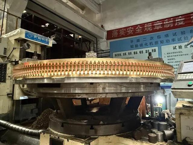
The two main parts of a Large Worm Gear are the worm shaft, which looks like a mechanical screw, and the worm wheel, which is a specially made gear with helical teeth. When the worm turns, its threads contact the wheel's teeth at an angle that is perpendicular to them, usually 90 degrees. This turns rotational input into a lot of power while slowed down a lot. What makes "large" versions different is their size—wheel widths often go over 500 mm and can reach up to 3 meters—which is why they are designed for big industrial uses where smaller models can't handle the load.
Critical Terminology for Procurement Teams
When sourcing, making sure that the specifications are correct means understanding complex terms. The lead is the axial distance that the worm moves in one full rotation. This has a direct effect on the gear ratio. Pitch is the distance along the pitch circle between two spots on two neighbouring teeth that are the same. Backlash is the small space between two teeth that fit together. It's needed to keep them from sticking when the temperature rises, but it needs to be carefully managed to keep the teeth in the right place. The tooth size and load capacity are determined by module specs that range from 1 to 50. The lead angle affects both efficiency and the important self-locking feature that stops spinning in reverse when lifting.
Material Selection Drives Performance Outcomes
To keep its surface from wearing down from constant sliding contact, the worm shaft needs to be very hard. We make these parts from high-quality alloy steels like 20CrMnTi, AISI 8620, and 42CrMo. We use advanced heat treatment methods like carburising and cooling to make the surfaces hard (58–62 HRC) while keeping the core strong and resistant to shock. A worm wheel usually has a steel or cast iron hub and a bronze rim that is often made by centrifugally casting tin-aluminum bronze alloys. This combination of materials makes for the best tribological properties: the harder steel worm going against the softer bronze reduces friction coefficients, and the bronze can handle small misalignments and gives great wear properties. The choice of material has a direct effect on how long something will work, especially in rough mining settings or high-cycle industrial computer systems.
Maximizing Efficiency and Performance of Large Worm Gears
Understanding Efficiency Factors in Worm Drive Systems
The efficiency of a Large Worm Gear depends a lot on the lead angle, the sliding speed, and the quality of the oil used. Single-reduction systems usually get between 50 and 95% efficiency, and as the lead angle gets higher, it gets closer to the upper range. Because worm threads and wheel teeth naturally slide against each other, they create more friction than rolling contact gears. This makes the greasing plan very important. Choose synthetic polyglycol lubricants with an ISO VG 460 or 680 rating for better film strength when boundary lubrication conditions exist. These lubricants also keep their viscosity stability over temperature changes that are common in heavy machinery enclosures.
To improve efficiency, you have to balance a lot of different factors during the planning step. Grinding the worm to tolerances of less than a micron lowers the surface roughness that leads to parasitic friction losses. In our production process, we use CNC gear grinding tools and advanced hobbing methods to keep the precision at an ISO 8–9 level, which makes sure that the tooth contact patterns are perfect. The blueing test, in which machinist's dye shows where the real contact areas are, proves that the engagement zones are wider than 60% along the length and 50% across the height. These are the levels that keep loads evenly distributed and stop premature pitting failure.
Maintenance Protocols That Extend Operational Life
The total cost of ownership is directly affected by scheduled maintenance. During the first 500 hours of operation, we suggest that you analyse the oil to get a standard count of the wear particles. After that, you should do this every three months. Ferrography finds bronze particles that show how fast wheels are wearing down, which lets you replace them before a major failure throws off production plans. An review of the lubrication system should make sure that the right amount of oil is getting to the mesh zones and that the right viscosity and fill levels are being used to keep the gears covered while the system is running.
By placing accelerometers near bearing housings and using vibration analysis, mismatches or misalignments can be found before they speed up the wear process. Infrared thermography is used to check the temperature and find localised hot spots that could mean that the bearings aren't well oiled or are overloaded. By finding problems during regular service windows instead of production runs, these diagnostic methods change maintenance from reactive crisis management to proactive condition tracking. This cuts down on unplanned downtime.
Noise and Vibration Mitigation Strategies
Large Worm Gear systems often have too much noise because of impacts between the teeth, broken bearings, or resonances that are amplified by mounting structures. Tooth-to-tooth variation that causes contact loading during engagement is kept to a minimum by using precise production standards. When properly oiled, the sliding action of worm gears makes them quieter to use than spur or helical alternatives. This is because the gradual engagement of helical teeth avoids the sudden loading that happens with straight-tooth designs.
We deal with shaking in a number of technical ways. When you carefully choose the gear module and tooth count, you can avoid hunting ratios that cause loading patterns that repeat. By putting the gears on elastomeric pads that isolate vibrations, working frequencies are kept from getting into the supporting structures. We specify tighter tolerance grades and dynamic balancing of rotating assemblies to ISO G6.3 standards for aerospace ground equipment and precision machine tool indexing mechanisms, which have strict noise limits. This makes operation measurably quieter, which makes operators more comfortable and extends the life of parts.
Comparing Large Worm Gears with Other Gear Types for Optimal Selection
Load Capacity and Torque Transmission Characteristics
When procurement teams look at different gearbox choices for heavy equipment, knowing how much power each one can handle helps them make the right choice. Large Worm Gear sets are great at handling shock loads because they have a lot of contact area between many teeth that are all engaged at the same time. This is different from spur gears, where the load is usually shared by only one or two tooth pairs. The sliding contact action also has built-in damping that absorbs torsional vibrations from machinery that moves back and forth or variable-torque applications, which are common in mining mill drives.
Efficiency Trade-offs Versus Application Requirements
When other factors become more important than efficiency, worm drives can be chosen even though they are less efficient than parallel-shaft drives. Elevator traction machines use the self-locking feature as a safety feature to keep the cabin from falling when the power goes out. This is something that helical or spur gears can't do without extra braking systems. In mining operations, conveyor systems are made to last because they work better in dirty, rough places where Large Worm Gear enclosed design and bronze wear surface work better than other configurations' exposed teeth.
Cost Considerations Across Gear Technologies
The cost of acquisition is only one part of the total owning economy. Large Worm Gear sets usually cost less than planetary systems of the same size because they are easier to put together—they only have two parts instead of multiple planet carriers, sun gears, and ring gears that need to be carefully put together. Maintenance costs stay low because the design is made up of two parts and replacing is easy. In hybrid designs, the bronze wheel rims can be changed separately from the steel hub. This extends the service life and keeps the cost of repairs low.
In production settings, the costs of downtime often go over the prices of the parts. When properly specified and maintained, worm gear systems are very reliable thanks to their strong, tried-and-true design. Our clients who use automated production line reducers say that the average time between failures is more than 50,000 hours when the machines are running at full capacity and maintenance schedules are followed. These kinds of reliability numbers make the technology choice worth it even when other types of gearbox might offer small efficiency gains.
Practical Applications and Case Studies of Large Worm Gears
Mining and Material Processing Equipment
Mining equipment faces dust, shock loads, continuous operation, and difficult maintenance conditions. Large worm gear drives support ball mill systems by reliably handling heavy loads with precise speed control. Their self-locking capability prevents conveyor rollback, while durable bronze wheels resist abrasive wear, extending service intervals and reducing costly maintenance downtime in harsh mining environments.
Elevator and Lifting Equipment Solutions
Safety rules for people lifting tools require redundant systems that stop the falling from happening without control. Large Worm Gear pulling machines are the main source of power, and they also have built-in mechanical backdriving resistance to keep things safe. Modern setups add specialised stop systems on top of this because that's what the law requires, but the worm gear's properties still help make the whole system safer. The smooth torque delivery keeps passengers as comfortable as possible when the vehicle speeds up or slows down, and the small perpendicular shaft design makes the best use of the machine room's limited space.
Machine Tool and Precision Positioning Systems
In CNC machining centers, indexing tables need to be able to position workpieces accurately to within arc seconds while clamping them tightly during cutting processes. High reduction ratios in worm gear drives give them the positioning accuracy they need, and their self-locking feature keeps them in place without needing constant motor power. This mechanical position holding cuts down on energy use and gets rid of the thermal drift that comes with brake systems or motors that are always engaged. Phosphor bronze wheels with precisely ground worm threads provide the smooth, backlash-free motion needed to keep dimensions within acceptable limits in the production of aerospace parts.
Automated production line reducers are another demanding application where dependability has a direct effect on the speed of production. Transmission parts must work continuously during multiple shifts for robotic assembly systems, automated guided vehicles, and conveyor networks to work. When worm gear systems are set up correctly, they last a long time and don't need as much unplanned maintenance, which slows down production. Our standard but flexible design approach lets us quickly integrate into a wide range of automation platforms while keeping the quality standards that production engineers need for reliable equipment performance.
Procurement Guide: How to Source the Best Large Worm Gears for Your Business
Evaluating Supplier Capabilities and Certifications
Comparing price quotes is only one part of successful shopping. Teams in charge of buying things should make sure that any possible providers follow ISO 9001 quality standards and have experience making gears. Ask for proof of the heat treatment skills because the right way to carburise and temper directly impacts the service life. Before sending goods out, suppliers should show that they have the right checking tools, such as coordinate measure machines to check the sizes, metallurgical laboratories to look at the materials' make-up, and gear rolling test stands to make sure the products work properly.
When getting bigger parts and diameters, manufacturing ability becomes very important. To make Large Worm Gears with more than 20 modules, you need big hobbing machines, heat treatment furnaces that can handle big parts, and grinding tools that can handle a lot of work and are rigid. We put a lot of money into high-precision manufacturing equipment to meet the needs of heavy industry. For example, we bought CNC gear grinding centers that can work with parts up to 2.5 meters in diameter and keep ISO 8 accuracy grades across the whole tooth profile.
Understanding Lead Times and Custom Manufacturing Processes
Catalogue gears that aren't made to order rarely meet the specific needs of heavy industrial applications. To make a custom product, the steps are as follows: analysing the needs and getting technical advice to come up with clear specifications; creating detailed engineering drawings; obtaining certified alloys that meet the standards; precision machining by cutting and hobbing; heat treatment using carburising or quenching protocols; finish grinding to achieve final dimensional tolerances; and finally, a thorough quality inspection before packaging and shipping.
Realistic wait times for special Large Worm Gear projects range from 35 to 60 days, based on how complicated the project is, how long it takes to make the parts, and how busy the production line is. Throughout this cycle, we keep communication open and honest by giving customers synchronised information on the progress of production that help them plan when to put the equipment and when to deliver it. Prioritising production can sometimes help with rush situations, but this needs to be talked about early on to see if it's possible and what the possible expedite effects might be.
Logistical Considerations for Large Components
To move heavy, precisely made gears presents special difficulties. Damage to the surface during transport or handling can change the shape of the teeth and require expensive repair. We came up with special ways to package things by using shock-absorbing padding liners and custom-made wooden pallets that are made to protect gear. This planned method lowers the chance of damage during transport to less than 0.1%. This protects your investment throughout the whole logistics chain, from our building to the installation site.
There are several ways to ship goods around the world. Sea freight is the most cost-effective way to send full containers, air freight is best for urgent needs, and China-Europe rail services are the best of both speed and economy for European targets. We offer visual tracking from start to finish, with real-time updates at every logistics milestone, such as loading at the plant, clearing customs, port transfers, and final delivery. This lets you keep an eye on the progress of your package and plan your receiving activities. This clarity gets rid of doubt and helps with just-in-time installation planning, which cuts down on equipment downtime during projects like commissioning or retrofitting.
Conclusion
To get the most out of a Large Worm Gear, you need to take a complete approach that includes proper design, quality production, and smart upkeep. When engineering teams choose the right materials, check the supplier's abilities, and put condition-based maintenance protocols into place, these strong gearbox parts perform better than any others in tough situations. Worm gear technology is unbeatable in industrial machinery, mining operations, and precision positioning systems because it has a high power capacity, a small size, and safety features that are built in. When you work with experienced manufacturers who offer advanced production techniques and quick technical support, these mechanical parts go from being simple parts to valuable assets that improve the reliability of your equipment, extend its useful life, and ultimately make you more competitive in your market segment.
FAQ
1.How often should Large Worm Gear systems undergo maintenance inspection?
How often maintenance is done depends on the job cycle and working conditions. We suggest that the oil be analysed for the first time after 500 hours of use to find out how it wears normally. For continuous-duty uses, this should be done every three months after that. Once a month, the lubrication system should be checked to make sure there are no contaminants and that the oil levels are correct. When equipment is used in harsh conditions like high temperatures, coarse dust, or shock loading, it should be checked more often using vibration analysis and thermography to find problems before they become major.
2.Can Large Worm Gear systems operate effectively in high-speed applications?
Large Worm Gear technology works best in situations where torque multiplication is more important than high output speeds. The sliding contact at the mesh interface creates heat that is proportional to speed. This means that the fastest speeds that can be used are usually around 1000 RPM, though this can change depending on how the cooling and lubrication system is set up. For uses that need higher speeds but still need small right-angle drive setups, different technologies like spiral bevel or hypoid gears may be better. These use rolling contact mechanics to work more efficiently at high speeds.
3.What indicators signal that a worm wheel requires replacement?
A visual inspection that shows tooth thickness has decreased by more than 20 to 25 percent from its original size is a sign that the service life is almost up. Higher running temps compared to the starting point could mean that the mesh shape or lubrication isn't working as well as it used to. The fact that oil research found high levels of bronze particles proves that wear is happening faster. Strange noises or vibrations during operation are signs that problems are starting to show up. Condition monitoring-based proactive replacement stops catastrophic failures that damage joining parts and cause long unexpected downtime that costs a lot more than planned maintenance.
Partner with YIZHI MACHINERY for Superior Large Worm Gear Solutions
The experts at YIZHI MACHINERY have been making precise gearbox parts for 15 years for use in mining, aerospace and industrial machinery. We can make custom Large Worm Gear modules from one to fifty. We use high-quality alloy steels like 20CrMnTi and AISI 8620, which are heated, cooled, and ground in advanced ways to reach ISO 8-9 precision grades and surface hardnesses of 58 to 62 HRC. We have low minimum order numbers and can even make a single piece for a prototype or an emergency replacement. We also offer full technical support to help you find the best gear specs for your unique needs.
Our all-in-one service model helps you with communicating your needs, engineering design, precision manufacturing, strict quality control, protective packaging, and tracked global logistics. Contact us at sales@yizmachinery.com to talk about your project needs with Large Worm Gear experts who have a lot of experience working in harsh industrial settings and can help you find the best solutions backed by ISO-compliant quality systems and quick after-sales support.
References
1. Dudley, D.W. (1994). Handbook of Practical Gear Design and Manufacture. CRC Press.
2. American Gear Manufacturers Association. (2004). AGMA 6034-B92: Practice for Enclosed Cylindrical Wormgear Speed Reducers and Gearmotors.
3. Litvin, F.L. & Fuentes, A. (2004). Gear Geometry and Applied Theory. Cambridge University Press.
4. ISO 2553:2013. Gears — Worm Gear Pairs — Geometry and Accuracy.
5. Buckingham, E. (1988). Analytical Mechanics of Gears. Dover Publications.
6. Davis, J.R. (2005). Gear Materials, Properties, and Manufacture. ASM International.

USER EVALUATE
Here is the customer's evaluation of us