


What Is a Worm Gear Pair and How Does It Work?
Worm Gear Pairs are a special kind of power transmission system that has two separate parts: the worm (a threaded rod that looks like a screw) and the Worm Wheel (a circular gear that fits inside the worm). These parts meet at a 90-degree angle on axes that don't touch each other. The worm's helical threads engage the Worm Wheel's teeth when the worm turns, changing the rotary motion while reducing speed and increasing torque by a large amount. The sliding contact between these parts gives them special mechanical benefits, like the ability to self-lock and small sizes, which solve important engineering problems in lift systems, lifting equipment and automated machinery where safety and limited space are very important.
Understanding Worm Gear Pairs: Definition and Working Principle
What Defines a Worm Gear Pair?
The way a Worm Gear Pair works is very different from how normal Parallel-Axis gearing works. The worm looks like a screw thread wrapped around a shaft, and the Worm Wheel has teeth that are cut at an angle to fit with those threads. This straight-line setup lets motion travel between shafts that are at right angles to each other, which makes these systems very useful in places with limited room.
The mechanical advantage comes from the lead angle of the worm, which is the angle at which the thread moves forward. In a single stage, reduction ratios can be anywhere from 5:1 to over 300:1. This means that there is no need for multi-stage gear trains, which would take up a lot more room. Because of this shape, companies that make lift traction machines and crane systems always choose Worm Gear Pair technology for their core reducers.
How Power Transmits Through the System
Instead of rolling contacts like in Spur Gears or Helical Gears, power is sent through slide contacts. When the worm turns, its threads push against the teeth of the Worm Wheel, making a tangential force that turns the wheel. When something slides against something else, there is more friction than when something rolls against something else. This lowers efficiency but also lowers vibration and noise.
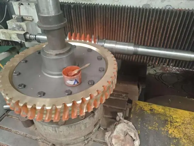
The way that parts touch each other is very important. The contact spot on the Worm Wheel teeth of a high-quality Worm Gear Pair is in the middle and slightly to the left. This gap lets the grease form a safe wedge, which keeps metal from touching metal and increases the life of the part. At YIZHI MACHINERY, our precise grinding processes make sure that the contact patterns are perfect by putting them through strict blueing tests as part of the quality checking process.
Material Selection and Its Engineering Impact
Pairing materials has a direct effect on how long they last and how well they work. Worm Gear Pairs of good quality usually have sharpened steel worms and lighter bronze wheels. The steel worm, which is made from 20CrMnTi or SAE4340, is hardened by carburising and quenching until its surface is between 58 and 62 HRC. This level of hardness stops pitting and wear that can happen because of the high contact loads that come with sliding mesh interaction.
Nickel-bronze alloys or phosphor bronze are often used in the Worm Wheel. This softer material gives up more easily during wear cycles to protect the more expensive and hard to replace worm. Also, the bronze is more flexible, which lets the contact patch form correctly during the running-in period. Worm Gear Pair systems in mine conveyors and stage lifting equipment can work successfully for years under tough conditions when they are made with this material strategy and properly oiled.
The Role of Precision Manufacturing
Transmission precision and noise levels are directly affected by manufacturing error. To get a surface sharpness below Ra 0.4µm, you have to carefully turn or hob the worm's spiral shape and then grind it. The Worm Wheel teeth are made by hobbing or forming metal in ways that exactly match the angle and pitch of the worm's lead.
Adding heat treatment adds another important factor. When you carburise something, you make the case harder so it can handle Hertzian stress while keeping the core tough so it can handle shock loads. Controlling the case depth and hardness gradients needs a lot of metalworking knowledge. Too little hardness causes pitting failure very quickly, and too much brittleness breaks teeth under shock loading. This is a common way that machine tool indexing mechanisms fail when they are put through quick start-stop cycles.
Advantages and Applications of Worm Gear Pairs in Industrial Settings
Before looking at specific benefits, it's important to understand how these mechanical advantages lead to real practical changes in a wide range of business settings. These are the main benefits of Worm Gear Pairs that make it essential for tough jobs:
- Compact High-Ratio Reduction: A 60:1 reduction ratio only needs one Worm Gear Pair stage, while a Spur Gear train would need three stages, which would take up three times as much space. This makes better use of space is very important in lift machine rooms where floor space is expensive. It also helps equipment makers make products that are more competitive.
- Inherent Self-Locking Capability: The system locks itself when the worm's lead angle drops below the friction angle, which is usually around 5 degrees. This means that the worm can move the wheel, but the wheel can't move backwards and drive the worm. This mechanical brake keeps loads from falling in hoist systems even when the power goes out. It gets rid of the need for extra brakes and makes stage lifting equipment safer.
- Smooth Silent Operation: The sliding contact naturally reduces torsional vibrations and gets rid of the gear noise that spur meshes make. In automatic production lines where noise pollution hurts worker happiness and shortens the life of equipment, worm reducers make the noise level 10-15 dB lower than similar Helical Gear systems.
- High Shock Load Absorption: The sliding contact spreads sudden loads across several teeth at the same time, reducing impact forces that would normally break teeth in traditional gearing. This shock-absorbing property is very helpful for mining machines that start up while they are full.
All of these benefits help solve problems that keep coming up in the creation of fine machinery. Crane winch system makers really like how self-locking safety and a small installation envelope work together to make hoists that can do more within standard size limits.
Real-World Implementation Success
Worm Gear Pair technology has been shown to be useful in a wide range of situations by major makers of industrial tools. Worm reducers are used as the main speed-reducing units in lift traction systems from major brands. These reducers have self-locking properties that keep passengers safe and meet building code requirements for smooth acceleration profiles.
Worm gear reducers are used in heavy-duty conveyor systems to start belts that are fully filled with tonnes of waste material. In these high-inertia situations, the built-in shock absorption stops the catastrophic tooth failures that happen with Spur Gear alternatives. Production leaders at mines say that repair intervals are 40–60% longer than they were with older Helical Gear installations.
Worm Gear Pairs give precision valve actuators in process control systems the mechanical edge they need to turn a valve a quarter of the way while high fluid pressures are present. When manufacturing standards are met, zero-backlash designs are possible. These designs allow exact flow modulation without the position drift that lowers the accuracy of process control.
Worm Gear Pair vs Other Gear Types: Making the Right Choice
Purchasing managers often have to choose between different types of Worm Gear Pair technologies, each of which has its own set of performance characteristics. Understanding these trade-offs will help you choose the best components for your application.
Efficiency Considerations
Worm Gear Pair efficiency is usually between 50 and 95%, but it depends on the reduction ratio and lead angle the most. When lead angles are bigger and ratios are lower (5:1 to 15:1), efficiency is higher. But when ratios are very high (above 100:1), efficiency may drop below 60%. Helical Gears or Planetary Gears, on the other hand, always work at 95–98% efficiency, no matter what the ratio is.
In continuous-duty uses, the difference in performance is very important. A 10 kW motor running a 70% efficient worm reducer loses 3 kW as heat, so it's important to have good thermal control. But in cases with intermittent service, like valve actuators that only work for a few minutes an hour, the loss of efficiency is almost negligible, and the benefits in terms of room and cost take precedence.
Load Capacity and Thermal Management
Worm Gear Pairs with sliding contacts make more heat than those with rolling contacts. This thermal loading limits the continuous-duty power ratings unless better cooling is put in place. It's important to choose the right gear oil. Synthetic lubricants with extreme-pressure ingredients keep the film strong at the high temperatures that Worm Gear Pairs need to work.
Planetary Gear sets are better for high-continuous-power applications because they can handle higher power densities in the same size spaces. But Worm Gear Pairs work great in cyclic-duty situations where their better ability to handle shock loads is more important than temperature concerns. Machine tool indexing mechanisms are a good example of this sweet spot—short moves with a lot of torque followed by long dwell times let the part cool down enough between cycles.
Maintenance Requirements and Service Life
Enclosed Helical Gear units don't need to be oiled as often as Worm Gear Pair systems do. Both parts are constantly worn down by the moving contact. The brass wheel gives up material to protect the steel worm. Monitoring the concentration of wear particles in the oil on a regular basis helps determine when maintenance needs to be done so that major problems don't happen.
Worm reducers in lift traction machines usually last between 15 and 20 years if they are well taken care of, but if they aren't oiled, they can break down within months. Setting up strict maintenance rules, like changing the oil every 2,500 to 5,000 hours of operation and measuring the backlash on a regular basis, will protect your investment and keep it from breaking down when you least expect it.
Troubleshooting, Maintenance, and Noise Reduction Strategies
Common Wear Patterns and Their Root Causes
Normal Worm Gear Pair wear shows up as tooth wear on the Worm Wheel, which can be seen as tooth surfaces that are polished or scored. Wear that is the same across the whole tooth face means that the teeth are in the right place and are properly oiled. When wear is concentrated on the edges of teeth, it means that the worm and wheel axes are not lined up correctly. This needs to be fixed right away to stop failure from speeding up.
Pitting on the worm threads means they are not hard enough or that the lubrication has broken down, letting metal touch metal. This usually shows up as small depressions on the sides of the teeth and gets worse over time until it breaks. When technical buying managers look for new parts, they make sure they get the right surface hardness (58–62 HRC for steel worms) and proof of heat treatment. This stops problems from happening again.
Effective Lubrication Strategies
Choosing the right gear oil has a big effect on how long it lasts. To keep the film strength when Worm Gear Pairs are used, they need lubricants with extreme-pressure additives. This is because Worm Gear Pairs have high sliding speeds and contact pressures. The ISO VG 220-460 viscosity grades are good for most industrial uses. Higher viscosities are used for high temperatures or heavy loads.
The amount of oil doesn't matter. Making sure the oil level is right keeps the lower half of the Worm Wheel submerged and lubricates all the mesh surfaces with splashes. When oil levels are low, the top tooth surfaces don't have enough lube, which speeds up wear. Supervisors of quality inspections should set up regular checks of the oil level—every week for critical equipment and every month for standard installations.
Diagnosing and Resolving Noise Issues
There are three main reasons why operating noise is usually too high: imbalance, poor backlash, or loss of surface roughness. A methodical approach to diagnosis finds the culprit. Noise that changes with load but stays the same at all speeds is a sign of backlash. If the sound gets louder as the speed goes up, it means that the surface is rough and the worm needs to be replaced.
Precision grinding of both the worm and the wheel after heat treatment to get mirror ends below Ra 0.4µm is an example of an advanced noise reduction strategy. Edge loading that causes high-frequency noise can be stopped by making changes to the profile that slightly loosen up the tooth tips and roots. These improvements, which are standard in the way YIZHI MACHINERY is made, make sure that the noise levels during operations are low enough to meet strict noise regulations in occupied spaces.
Establishing Repair vs. Replacement Criteria
Repair choices should be based on economic research. When Worm Wheel wear goes over 0.5 mm or worm thread height loss goes over 10%, it's cheaper to replace the part than to try to fix it by welding and machining again. Repairing something often costs more than buying a new part from a well-known seller because of the labour involved and the unknown results of the metalworking.
Keeping spare parts on hand is a good idea for important production equipment that costs more than $5,000 per day to shut down. For equipment that is past 60% of its expected service life, production directors should keep full Worm Gear Pair sets on hand. This will allow for quick changes that keep production running as smoothly as possible.
Procurement Insights: How to Source and Purchase Worm Gear Pairs
Evaluating Supplier Capabilities
To choose the right Worm Gear Pair provider, you need to look at more than just price quotes. Quality certifications are the first thing that are looked at. For example, ISO 9001 certification means that the process controls have been set up, and ISO 8-9 grade precision specs make sure that the dimensions are accurate enough for demanding uses.
Technical help skills are what set good providers apart from great partners. Can the provider help you with application engineering to make sure that the gear specs are best for the way you'll be loading it? Do they offer finite element analysis to make sure designs work before making the tools for production? These value-added services make your tech job easier while also making the product work better.
Manufacturing tools has a direct effect on the quality that can be made. When it comes to precision, suppliers who have CNC gear grinding machines and Coordinate Measuring Machines (CMM) are miles ahead of those who only use hobbing machines. When looking for Worm Gear Pairs for lift traction machines that need to run quietly, make sure the parts are ground and the surface finishes are checked.
Understanding Pricing Structures and Customization Options
Standard catalogue worm gear parts are cheapest but offer limited flexibility, while custom worm gear pairs cost more yet provide better performance and application fit, becoming cost-effective above 50–100 units annually. Material choice strongly affects pricing: 45# steel is cheaper, whereas SAE4340 or 18CrNiMo7 offer 2–3× longer life. Lifecycle cost often justifies higher upfront investment. YIZHI MACHINERY provides customizable solutions (module 1–50) with low minimum order quantities and fast lead times.
Building Strategic Supplier Partnerships
Transactional purchasing focuses mainly on price, often at the expense of quality and technical support, whereas strategic supplier partnerships create long-term value through collaboration and continuous improvement. Open technical communication enables design optimization and early issue detection, reducing costly failures. Effective partnerships rely on shared application data. Lead times vary by region, with international suppliers offering cost efficiencies and logistics support, including sea, air, and rail shipping, plus real-time order tracking for supply chain visibility.
Conclusion
Worm Gear Pairs have special mechanical benefits, such as small high-ratio reduction, self-locking safety features, and smooth, quiet operation. These benefits help lift equipment, automatic machinery, and precision positioning systems solve long-standing problems. By knowing how they work, what materials they need, and how often they need to be maintained, you can make smart purchasing choices that balance the original cost with the long-term value. By comparing performance features of Worm Gear Pair technology to those of other gear types, it becomes clear where worm technology shines and where other options are better. For implementation to go smoothly, you need to work with suppliers who can provide more than just parts. These suppliers should have technical knowledge, quality certifications, and quick response times.
FAQ
1.What makes worm gear pairs self-locking?
When the Worm Gear Pair's lead angle drops below the friction angle between the meeting surfaces, which is usually around 5 degrees, the worm locks itself in place. In this case, friction forces stop the Worm Wheel from moving the worm backwards, which makes a built-in mechanical brake. In hoisting uses, this safety feature keeps things from falling even when the power goes out.
2.How long do worm gear pairs typically last?
Service life is very different depending on the duty cycle, quality of the lubrication, and load conditions. Elevator traction machines have systems that last 15 to 20 years if they are properly maintained. However, units that aren't oiled properly and are used in harsh environments may break down in 12 to 24 months. Regular oil analysis and reaction tracking allow for planned repair that extends the life of parts the most.
3.Can worm gear efficiency be improved?
Efficiency improves through lower reduction ratios, larger lead angles, better surface finishes, and better lubricants all make machines more efficient. Getting the worm and wheel to a mirror shine below Ra 0.4 µm lowers the friction that makes them slide. When compared to regular mineral oils, synthetic lubricants with friction modifiers can make things work 5 to 10 percent better.
Partner with YIZHI MACHINERY for Premium Worm Gear Pair Solutions
Technical purchasing managers and reducer design engineers looking for dependable Worm Gear Pair manufacturers will find that YIZHI MACHINERY is in a unique position to meet their needs. Our manufacturing processes are in line with ISO standards, and the parts we make are precision-ground from high-quality materials like 20CrMnTi and SAE4340. The surfaces are then heated to 58–62 HRC to make them as durable as possible. We make unique Worm Gear Pairs with modules running from 1 to 50. These can be used in a wide range of situations, from heavy-duty crane reducers to small machine tool indexing mechanisms.
Our full customisation process includes requirement conversation, design drawing validation, precision machining, strict quality inspection, protective packing, and tracked shipping to make sure that the parts we deliver match your exact specs. We offer advanced CMM inspection equipment, 35–60 day lead times, and 15 years of manufacturing experience in the lift, mining, and automation industries. We are the technical partner your projects deserve. Contact us at sales@yizmachinery.com to talk about your unique worm gear needs and get thorough technical proposals.
References
1. Dudley, Darle W. Handbook of Practical Gear Design and Manufacture. CRC Press, 2016.
2. American Gear Manufacturers Association. AGMA 6022-C93: Design Manual for Cylindrical Worm Gearing. AGMA, 1993.
3. Colbourne, J.R. The Geometry of Involute Gears. Springer-Verlag, 1987.
4. Deutsches Institut für Normung. DIN 3996: Calculation of Load Capacity of Cylindrical Worm Gear Pairs with Rectangular Crossing Axes. Beuth Verlag, 2012.
5. Litvin, Faydor L., and Fuentes, Alfonso. Gear Geometry and Applied Theory. Cambridge University Press, 2004.
6. Buckingham, Earle. Analytical Mechanics of Gears. Dover Publications, 1988.

USER EVALUATE
Here is the customer's evaluation of us